|
Current Manual/ Settlement |
IBHS Draft |
Comments |
||||||||||||||||||||||||||||||||||||||||
|
101 Retrofits Required. Pursuant to Section 553.844, Florida
Statutes, strengthening of existing site-built, single family residential
structures to resist hurricanes shall be provided. |
101 Retrofits Required. Pursuant to Section 553.844, Florida
Statutes, strengthening of existing site-built, single family residential
structures permitted prior to the implementation of the 2001 |
|
||||||||||||||||||||||||||||||||||||||||
|
101 Retrofits
Required. Pursuant to Section
553.844, Florida Statutes, strengthening of existing site-built, single
family residential structures to resist hurricanes shall be provided. Site built single-
family residential structures shall mean site built single family detached
residential structures. |
|
Settlement |
||||||||||||||||||||||||||||||||||||||||
|
101.1 When a roof on an existing site-built, single family residential structure is replaced: (a) Roof-decking attachment and fasteners shall be strengthened and corrected as required by section 201.1. (b) A secondary water barrier shall be provided as required by section 201.2. |
101.1 When a roof covering on an existing site-built, single family residential structure is replaced: (a) Roof-decking
attachment and fasteners shall be strengthened and corrected, in those
areas of the building where the roof covering is removed, as required by
section 201.1. (b) A secondary water barrier shall be provided as required by section 201.2. |
|
||||||||||||||||||||||||||||||||||||||||
|
101.1 When a roof on an existing site-built, single family residential structure is replaced, the following procedures shall be permitted to be performed by the roofing contractor: (a) Roof-decking attachment and fasteners shall be strengthened and corrected as required by section 201.1. (b) A secondary water barrier shall be provided as required by section 201.2. |
|
Settlement |
||||||||||||||||||||||||||||||||||||||||
|
101.2 When a roof is replaced on a
building that is located in the wind-borne debris region as defined in s.
1609.2 of the (a) Roof to wall connections shall be improved
as required by section 201.3. (b) Mandated retrofits of the roof-to-wall
connection shall not be required beyond a 15 percent increase in the cost of
re-roofing. (c) Where complete retrofits of all the roof-to-wall connections as prescribed in Section 201.3 would exceed 15 percent of the cost of the re-roofing project, the priorities outlined in Section 201.3.5 shall be used to limit the scope of work to the 15 percent limit. |
No change. |
|
||||||||||||||||||||||||||||||||||||||||
|
101.2 When a roof is replaced on a
building that is located in the wind-borne debris region as defined in s.
1609.2 of the (a) Roof to wall connections shall be improved
as required by section 201.3. (b) Mandated retrofits of the roof-to-wall
connection shall not be required beyond a 15 percent increase in the cost of
re-roofing. (c) Where complete retrofits of all the
roof-to-wall connections as prescribed in Section 201.3 would exceed 15
percent of the cost of the re-roofing project, the priorities outlined in
Section 201.3.7 |
|
Settlement |
||||||||||||||||||||||||||||||||||||||||
|
101.3 When
any activity requiring a building permit that is applied for on or after July
1, 2008, and for which the estimated cost is $50,000 or more for a building
that is located in the wind borne debris region as defined in s. 1609.2 of
the (a) Opening
protections as required within the |
No change. |
|
||||||||||||||||||||||||||||||||||||||||
|
101.4 When retrofit enhancement of gable end bracing is provided during construction which otherwise requires a permit the techniques in Appendix A shall be allowed. |
101.4 When retrofit enhancement of gable end
bracing is to be provided |
See Ray Burrough’s
comment below. See Mike Moore’s
comment below. |
||||||||||||||||||||||||||||||||||||||||
|
201
Roof System Mitigation
Techniques. Roof sheathing fastening,
secondary water barriers, roof to wall connection and gable end bracing shall
be permitted pursuant to this section. |
No change. |
|
||||||||||||||||||||||||||||||||||||||||
|
201.1 Roof
sheathing fastening for site-built
single family residential structures. For site-built
single family residential structures the
fasteners and spacing required in Table 201.1 are deemed to comply with the
requirements of Section 507.2.2, of the 2004 |
201.1 Roof decking
Fastening shall be
in accordance with section 201.1.1 or 201.1.2. as appropriate for the
existing construction. 8d nails shall be a minimum of 0.141 inch in diameter
and shall be a minimum of 2-1/4 inch long to qualify for the provisions of
this section for existing nails regardless of head shape or head diameter. |
See FRSA comment
below. See Mike Moore comment below. |
||||||||||||||||||||||||||||||||||||||||
|
Board roof decking
secured with at least two 8d nails into roof framing members shall be deemed
to be sufficiently connected. Board
roof decking secured with smaller fasteners than 8d nails or with fewer than
two 8d nails per board shall be deemed sufficiently connected if two 8d
clipped head, round head, or ring shank nails are in place on each framing
member. |
|
|
||||||||||||||||||||||||||||||||||||||||
|
|
201.1.1 Roof
decking consisting of sawn lumber or wood planks up to 12” wide and secured
with at least two nails (minimum size 8d) to each roof framing member it
crosses shall be deemed to be sufficiently connected. Sawn lumber or wood plank decking secured
with smaller fasteners than 8d nails or with fewer than two nails (minimum size
8d) to each framing member it crosses shall be deemed sufficiently connected
if fasteners are added such that two clipped head, round head, or ring shank
nails (minimum size 8d) are in place on each framing member it crosses. |
|
||||||||||||||||||||||||||||||||||||||||
|
|
201.1.2 For
roof decking consisting of wood structural panels, fasteners and spacing
required in columns 3 and 4 of Table 201.1.2 are deemed to comply with the
requirements of Section 507.2.2, |
|
||||||||||||||||||||||||||||||||||||||||
|
Supplemental fasteners as required by Table 201.1 shall be 8d
ring shank nails with round heads and the following minimum dimensions: 1. 0.113 inch nominal shank diameter 2. Ring diameter of 0.012 over shank diameter 3. 16 to 20 rings per inch 4. 0.280 inch full round head diameter 5. 2-1/4 inch nail length |
Supplemental fasteners as required by Table 201. 1. 0.113-inch nominal shank diameter 2. Ring diameter a minimum of 0.012-inch 3. 16 to 20 rings per inch 4. a minimum 0.280-inch full
round head diameter 5. 2-1/4 inch minimum nail length |
|
||||||||||||||||||||||||||||||||||||||||
|
Supplemental fasteners as required by Table 201.1 shall be 8d
ring shank nails with round heads and the following minimum dimensions: 1. 0.113 inch nominal shank diameter 2. Ring diameter of 0.012 over shank diameter 3. 16 to 20 rings per inch 4. 0.280 inch full round head diameter 5. Ring shank to extend a minimum of 1 ½” from the tip of
the nail. 6. Minimum 2-1/4 inch nail length |
|
Settlement |
||||||||||||||||||||||||||||||||||||||||
|
Table 201.1 Supplement Fasteners at Panel Edges and
Intermediate Framing
a. Maximum spacing determined based on
existing fasteners and supplemental fasteners. b. Maximum spacing determined based on
supplemental fasteners only. |
Table 201.1 Supplement Fasteners at Panel Edges and
Intermediate Framing
a. Maximum spacing determined based on
existing fasteners and supplemental fasteners. b. Maximum spacing determined based on
supplemental fasteners only. |
See below for
proposed changes in the table. |
||||||||||||||||||||||||||||||||||||||||
|
Table 201.1 Supplement Fasteners at Panel Edges and
Intermediate Framing
a. Maximum spacing determined based on
existing fasteners and supplemental fasteners. b.
Maximum spacing determined based on supplemental fasteners only. |
|
Settlement |
||||||||||||||||||||||||||||||||||||||||
|
201.2 Roof secondary water barrier for site-built
single family residential structures. A
secondary water barrier shall be installed using one of the following methods
when roofing replacement when reroofing.
|
201.2 Roof secondary water barrier for site-built
single family residential structures. A
secondary water barrier shall be installed using one of the following methods
during |
See Christ Schulte’s, FRSA’s, Mike Moore’s, and Bill Dumbaugh’s comments below. |
||||||||||||||||||||||||||||||||||||||||
|
201.2 Roof secondary water barrier for site-built
single family residential structures. A
secondary water barrier shall be installed using one of the following methods
when |
|
Settlement |
||||||||||||||||||||||||||||||||||||||||
|
a) All joints in roof sheathing or decking
shall be covered with a minimum 4 in. wide strip of self-adhering polymer
modified bitumen tape applied directly to the sheathing or decking. The deck and self adhering polymer modified
bitumen tape shall be covered with one of the underlayment systems approved
for the particular roof covering to be applied to the roof. |
a) No change. |
|
||||||||||||||||||||||||||||||||||||||||
|
a) All joints in structural panel roof
sheathing or decking shall be covered with a minimum 4 in. wide strip of
self-adhering polymer modified bitumen tape applied directly to the sheathing
or decking. The deck and self adhering
polymer modified bitumen tape shall be covered with one of the underlayment
systems approved for the particular roof covering to be applied to the roof. |
|
Settlement |
||||||||||||||||||||||||||||||||||||||||
|
b) The entire roof deck shall be covered with
an approved self-adhering polymer modified bitumen cap sheet. No additional underlayment shall be
required on top of this cap sheet for new installations. |
b) No change. |
|
||||||||||||||||||||||||||||||||||||||||
|
b) The entire roof deck shall be covered with
an approved self-adhering polymer modified bitumen |
|
Settlement |
||||||||||||||||||||||||||||||||||||||||
|
c) The entire roof deck shall be covered with an approved asphalt
impregnated 30# felt underlayment installed with nails and tin-tabs as
required for the HVHZ. (No additional
underlayment shall be required over the top of this sheet). |
|
Settlement |
||||||||||||||||||||||||||||||||||||||||
|
d) Outside
of the HVHZ, an underlayment complying with
section 1507.2.3 of the |
|
Settlement |
||||||||||||||||||||||||||||||||||||||||
|
EXCEPTIONS: 1.
An asphalt impregnated 30# felt underlayment
installed with nails and tin-tabs as required for the HVHZ and covered with
either an approved self-adhering polymer modified bitumen cap sheet or an
approved cap sheet applied using an approved hot-mop application shall be
deemed to meet the requirements for the secondary water barrier. |
EXCEPTIONS: 1. An asphalt impregnated 30#
felt underlayment installed |
|
||||||||||||||||||||||||||||||||||||||||
|
|
2. A
reinforced synthetic underlayment with an ICC approval as an alternate to
ASTM D226 felt paper meeting ASTM D1970 nail sealing requirements and having
a minimum tear strength per ASTM D1970 or ASTM D4533 of 20 lbs. This underlayment, when attached using
annular ring or deformed shank roofing fasteners with minimum 1-inch diameter
metal or plastic caps at the spacing required by the manufacturer for high
wind installations or code requirements if more stringent; and, when all
seams are sealed with a compatible adhesive or compatible 4-inch wide tape,
shall be deemed to meet the requirements for the secondary water barrier. 3.
Application of a two-part urethane based closed cell spray-on adhesive to the
attic side of the joints between the sheathing shall be deemed to meet the
requirements for the secondary water barrier. |
|
||||||||||||||||||||||||||||||||||||||||
|
Exceptions: 1. Roof slopes < 2:12 having a continuous roof
system shall be deemed to comply with section 201.2 requirements for a
secondary water barrier. 2. Clay and Concrete tile roof systems installed
as required by the
|
|
Settlement |
||||||||||||||||||||||||||||||||||||||||
|
201.3 Roof-to-wall connections for site-built single family
residential structures. Where required by Section 101.2,
the intersection of roof framing with the wall below shall be strengthened by
adding metal connectors, clips, straps, and fasteners such that the
performance level equals or exceeds the uplift capacities as specified in
Table 201.3. As an alternative to an
engineered design, the prescriptive retrofit solutions provided in Sections
201.3.1 through 201.3.4 shall be accepted as meeting the mandated roof-to-wall
retrofit requirements. |
201.3 Roof-to-wall connections for site-built single family residential
structures. Where required by
section 101.2, the intersection of roof framing with the wall below shall |
|
||||||||||||||||||||||||||||||||||||||||
|
201.3 Roof-to-wall connections for site-built single family
residential structures. Where required by Section 101.2,
the intersection of roof framing with the wall below shall be strengthened by
adding metal connectors, clips, straps, and fasteners such that the
performance level equals or exceeds the uplift capacities as specified in
Table 201.3. As an alternative to an
engineered design, the prescriptive retrofit solutions provided in Sections
201.3.3 |
|
Settlement |
||||||||||||||||||||||||||||||||||||||||
|
Exceptions: 1. Where it can be demonstrated (by code
adoption date documentation and permit issuance date) that roof-to-wall
connections and/or roof-to-foundation continuous load path requirements were
required at the time of original construction. 2. Roof- to- wall
connections shall not be required unless evaluation and installation of
connections at gable ends or all corners can be completed for 15% of the cost
of roof replacement. |
|
Settlement |
||||||||||||||||||||||||||||||||||||||||
|
|
201.3.1 Access
for Retrofitting Roof to Wall Connections.
These provisions are not intended to limit the means for
gaining access to the structural elements of the roof and wall for the
purposes of retrofitting the connection.
The retrofit of roof to wall connections can be made by access
through the area under the eave, from above through the roof, or from the
interior of the house. Methods for
above access include removal of roof panels or sections thereof or removal of
portions of roof paneling by in effect making holes at selected locations
large enough for access, viewing, and installing the retrofit connectors and
fasteners. Where panels or sections are removed, the removed
portions shall not be reused. New
paneling shall be used and fastened as in new construction. Holes shall be deemed adequately repaired if a patch of
paneling is installed with no gap greater than ½ inch between the patch and
the existing sheathing and if the patch is supported using one of the
following methods. |
|
||||||||||||||||||||||||||||||||||||||||
|
|
a) Solid
1-1/2 inch lumber shall fully support the patch and shall be secured to the
existing sheathing with #8 by 1-1/4 inch screws spaced a minimum of 3” around
the perimeter with screws a minimum of ¾ inch from the near edge of the
hole. The patch shall be secured to
the lumber with #8 x 1-1/4 inch screws spaced on a grid no greater than 6
inches by 6 inches with no fewer than 2 screws. b)
Holes that extend horizontally from roof
framing member to adjacent roofing framing member that are less than or equal
to 7” wide along the slope of the roof
shall be supported by minimum of 2x4 lumber whose face is attached to
each roofing framing members using a minimum of 2 each 3-inch long fasteners
(#8 screws or 10d common nails)
connecting the two. The patch shall
have attached to its bottom running horizontally a minimum 2x4 either flat wise
or on edge secured with #8 x 1-1/4 inch screws a maximum of 4 inches on center
and no more distant from the end of the added lumber than 3 inches. The patch shall be secured with two #8 x
1-1/4 inch screws to each support member. |
|
||||||||||||||||||||||||||||||||||||||||
|
201.3.1 Access for Retrofitting Roof to
Wall Connections. These provisions are not intended to limit
the means for gaining access to the structural elements of the roof and wall
for the purposes of retrofitting the connection. The retrofit of roof to wall connections can be made by access
through the area under the eave, from above through the roof, or from the
interior of the house. Methods for
above access include removal of roof panels or sections thereof or removal of
portions of roof paneling at selected locations large enough for access,
viewing, and installing the retrofit connectors and fasteners. Where panels or
sections are removed, the removed portions shall not be reused. New paneling shall be used and fastened as
in new construction. |
|
Settlement |
||||||||||||||||||||||||||||||||||||||||
|
201.3.2 Partially inaccessible straps: Where part of a strap is inaccessible,
if the portion of the strap that is observed is fastened in compliance with
these requirements, the inaccessible portion of the strap shall be presumed
to comply with these requirements. |
|
Settlement |
||||||||||||||||||||||||||||||||||||||||
|
201.3.1 Prescriptive method for gable roofs
on a wood frame wall. Sufficient eave sheathing shall be removed
to expose a minimum of 6-feet of framing members, measured from the corner,
along the exterior wall on each side of each gable end. The anchorage of each of the exposed
rafters or truss shall be inspected. Wherever
a strap is missing or an existing strap has fewer than four fasteners on each
end, approved straps, ties or right angle gusset brackets with a minimum
uplift capacity of 500 lbs shall be installed that connect each rafter or
truss to the top plate below. Adding
fasteners to existing straps shall be allowed in lieu of adding a new strap
provided the strap is manufactured to accommodate at least 4 fasteners at
each end. Wherever access makes it
possible (without damage of the wall or soffit finishes), both top plate
members shall be connected to the stud below using a stud to plate connector
with a minimum uplift capacity of 500 lbs. |
201.3.2 |
|
||||||||||||||||||||||||||||||||||||||||
|
201.3.3 |
|
Settlement |
||||||||||||||||||||||||||||||||||||||||
|
201.3.2 Prescriptive method for gable roofs
on a masonry wall. Sufficient eave sheathing shall be removed
to expose a minimum of 6-feet of framing members, measured from the corner,
along the exterior wall on each side of each gable end. The anchorage of each of the exposed
rafters or truss shall be inspected. Wherever
a strap is missing or an existing strap has fewer than four fasteners on each
end, approved straps, ties or right angle gusset brackets with a minimum
uplift capacity of 500 lbs shall be installed that connect each rafter or
truss to the top plate below or directly to the masonry wall using approved
masonry screws that will provide at least a 2-1/2 embedment into the concrete
or masonry. When the straps or right
angle gusset brackets are attached to a wood sill plate, the sill plate shall
be anchored to the concrete masonry wall below. This anchorage shall be accomplished by
installing ¼-inch diameter masonry screws, each with supplementary ¼-inch
washer, having sufficient length to develop a 2-1/2 inch embedment into the
concrete and masonry. These screws
shall be installed within 4-inches of the truss or rafter on both sides of
each interior rafter or truss and on the accessible wall side of the gable
end truss or rafter. |
201.3.3 |
|
||||||||||||||||||||||||||||||||||||||||
|
201.3.4 |
|
Settlement |
||||||||||||||||||||||||||||||||||||||||
|
201.3.3 Prescriptive method for hip roofs
on a wood frame wall. Sufficient corner eave sheathing shall be
removed from the side of the hip ridge parallel to the roof ridge to provide
access to a minimum 6-foot length of the exterior wall. The hip ridge board and any exposed rafters
that are not anchored with a strap having at least four fasteners on each
end, shall be connected to the top plate below using a strap or a right angle
gusset bracket having a minimum uplift capacity of 500 lbs. Adding fasteners to existing straps shall
be allowed in lieu of adding a new strap provided the strap is manufactured
to accommodate at least 4 fasteners at each end. Wherever access makes it possible (without
damage of the wall or soffit finishes), both top plate members shall be
connected to the stud below using a stud to plate connector with a minimum
uplift capacity of 500 lbs. |
201.3. |
|
||||||||||||||||||||||||||||||||||||||||
|
201.3.5 |
|
Settlement |
||||||||||||||||||||||||||||||||||||||||
|
201.3.4 Prescriptive method for hip roofs
on a masonry wall. Sufficient corner eave sheathing shall be
removed from the side of the hip ridge parallel to the roof ridge to provide
access to a minimum 6-foot length of the exterior wall. The hip ridge board and any exposed rafters
that are not anchored with a strap having at least four fasteners on each
end, shall be connected to the concrete masonry wall below using approved
straps or right angle gusset brackets with a minimum uplift capacity of 500
lbs. Adding fasteners to existing
straps shall be allowed in lieu of adding a new strap provided the strap is
manufactured to accommodate at least 4 fasteners at each end. The straps or right angle gusset brackets
shall be installed such that they connect each rafter or truss to the top
plate below or directly to the masonry wall using approved masonry screws
that will provide at least a 2-1/2 embedment into the concrete or
masonry. When the straps or right
angle gusset brackets are attached to a wood sill plate, the sill plate shall
be anchored to the concrete masonry wall below. This anchorage shall be accomplished by
installing ¼-inch diameter masonry screws, each with supplementary ¼-inch
washer, with sufficient length to develop a 2-1/2 inch embedment into the
concrete and masonry. These screws
shall be installed within 4-inches of the truss or rafter on both sides of
each interior rafter or truss and on the accessible wall side of the gable
end truss or rafter. |
201.3.5 |
|
||||||||||||||||||||||||||||||||||||||||
|
201.3.6 |
|
Settlement |
||||||||||||||||||||||||||||||||||||||||
|
201.3.5 Priorities for mandated
roof-to-wall retrofit expenditures. For houses with both hip and
gable roof ends, the priority shall be to retrofit the gable end roof-to-wall
connections unless the width of the hip end is more than 1.5 times greater
than the width of the gable end. Priority
shall be given to connecting the corners of roofs to walls below where the
spans of the roofing members are greatest. |
201.3.6 |
|
||||||||||||||||||||||||||||||||||||||||
|
201.3.7 |
|
Settlement |
||||||||||||||||||||||||||||||||||||||||
|
Table
201.3 Required Uplift Capacities for Roof-to-Wall
Connections (POUNDS PER LINEAR FOOT) |
|
See table and Ray
Burrow’s comment below. |
||||||||||||||||||||||||||||||||||||||||
|
A101.1 Intent and purpose. The provisions of this subsection provide prescriptive solutions for
the retrofitting of gable ends of buildings. The retrofit measures are not
intended to provide strengthening |
A101.1 Intent and purpose. The provisions of this subsection provide prescriptive solutions for
the retrofitting of gable ends of buildings. The retrofit measures are |
|
||||||||||||||||||||||||||||||||||||||||
|
A101.2 Scope.
The following
prescriptive methods are intended for applications where the gable end wall
framing is provided by a wood gable end wall truss or a conventionally framed
rafter system. The retrofits are
appropriate for wall studs oriented with their broad face parallel to or
perpendicular to the gable wall surface.
An overview perspective drawing of the retrofit is shown in Figure
A104.1. |
No change. |
|
||||||||||||||||||||||||||||||||||||||||
|
ANCHOR BLOCK. A nominal 2-inch thick by at least 4” wide piece of lumber
secured to horizontal braces and filling the gap between existing framing
members for the purpose of restraining horizontal braces from movement perpendicular
to the framing members. |
No change. |
|
||||||||||||||||||||||||||||||||||||||||
|
COMPRESSION
BLOCK. A nominal 2-inch thick
by at least 4” wide piece of lumber used to restrain in the
compression mode (force directed towards the interior of the attic) an
existing or retrofit stud. It is
attached to a horizontal brace and bears directly against the existing or
retrofit stud. |
No change. |
|
||||||||||||||||||||||||||||||||||||||||
|
CONVENTIONALLY
FRAMED GABLE END. A conventionally framed gable end with
studs whose faces are perpendicular to the gable end wall. |
No change. |
|
||||||||||||||||||||||||||||||||||||||||
|
HORIZONTAL
BRACE. A nominal 2-inch thick
by at least 4” wide piece of lumber used to restrain both compression
and tension loads applied by a retrofit stud.
It is typically installed horizontally on the top of floor framing
members (truss bottom chords or ceiling joists) or on the bottom of pitched
roof framing members (truss top chord or rafters). |
No change. |
|
||||||||||||||||||||||||||||||||||||||||
|
RETROFIT STUD. A
nominal 2-inch lumber member used to structurally supplement an existing
gable end wall stud. |
No change. |
|
||||||||||||||||||||||||||||||||||||||||
|
RIGHT ANGLE GUSSET BRACKET. A
14 gage or thicker metal right angle bracket with a minimum load capacity
perpendicular to the plane of either face of 350 lbs when connected to wood
or concrete with manufacturer specified connectors. |
RIGHT ANGLE |
|
||||||||||||||||||||||||||||||||||||||||
|
STUD-TO-PLATE CONNECTOR. A
manufactured metal connector designed to connect studs to plates with a
minimum uplift capacity of 500 lbs. |
No change. |
|
||||||||||||||||||||||||||||||||||||||||
|
TRUSS GABLE
END. An engineered factory made truss or site
built truss that incorporates factory installed or field installed vertical
studs with their faces parallel to the plane of the truss and are spaced no
greater than 24-inches on center. Web
or other diagonal members other than top chords may or may not be
present. Gable end trusses may be of
the same height as nearby trusses or may be drop chord trusses in which the
top chord of the truss is lower by the depth of the top chord or outlookers. |
No change. |
|
||||||||||||||||||||||||||||||||||||||||
|
A103.1 Existing materials. All existing wood materials
that will be part of the retrofitting work (trusses, rafters, ceiling joists,
top plates, wall studs, etc.) shall be in sound condition and free from
defects or damage that substantially reduce the load-carrying capacity of the
member. Any wood materials found to be
damaged or deteriorated shall be strengthened or replaced with new materials
to provide a net dimension of sound wood equivalent to its undamaged original
dimensions. |
No change. |
|
||||||||||||||||||||||||||||||||||||||||
|
A103.2
New Materials. All materials approved by
this code, including their appropriate allowable stresses, shall be permitted
to meet the requirements of this chapter. |
No change. |
|
||||||||||||||||||||||||||||||||||||||||
|
A103.3 Dimensional Lumber. All dimensional lumber for braces, studs,
and blocking shall conform to applicable standards or grading rules. Dimensional lumber shall be identified by a
grade mark of a lumber grading or inspection agency that has been approved by
an accreditation body that complies with DOC PS 20. All new dimensional lumber to be used for
retrofitting purposes shall be a minimum grade and species of #2
Spruce-Pine-Fir or shall have a specific gravity of 0.42 or greater. In lieu of a grade mark, a certificate of
inspection issued by a lumber grading or inspection agency meeting the
requirements of this code shall be accepted. |
No change. |
|
||||||||||||||||||||||||||||||||||||||||
|
A103.4 Metal Plate
Connectors, Straps and Anchors. Metal
plate connectors, straps and anchors shall have product approval. They shall be approved for connecting
wood-to-wood or wood-to-concrete as appropriate. Straps
and tie plates shall be manufactured from galvanized steel with a minimum
thickness provided by 20 gauge. Tie
plates shall have holes sized for 8d nails. |
No change. |
|
||||||||||||||||||||||||||||||||||||||||
|
A103.5 Twists
in straps. Straps shall be permitted to be
twisted 90 degrees in addition to a 90 degree bend where they transition
between framing members or connection points.
|
A103.5 Twists
in straps. Straps shall be permitted to be
twisted 90 degrees in addition to a 90 degree bend where they transition
between framing members or connection points.
Straps shall be bent only once at a given location though it is
permissible that they be bent or twisted at multiple locations along their
length. |
|
||||||||||||||||||||||||||||||||||||||||
|
A103.6 Fasteners. Fasteners
meeting the requirements of Sections A103.6.1 and A103.6.2 shall be used and
shall be permitted to be screws or nails meeting the minimum length
requirement shown in figures and specified in tables. |
No change. |
|
||||||||||||||||||||||||||||||||||||||||
|
A103.6.1
Screws. Screws shall be a minimum #8
size with head diameters no
less than 0.3 inch. Screw lengths
shall be no less than indicated in the Figures and in Tables. Permissible
screws include deck screws, wood screws, or sheet metal screws
(without drill bit type tip, but can be sharp pointed). Screws shall have at least 1 inch of
thread. Fine threaded screws or
drywall screws shall not be permitted.
Note that many straps will not accommodate screws larger than #8. |
No change. |
|
||||||||||||||||||||||||||||||||||||||||
|
A103.6.2 Nails. Unless otherwise indicated in the
provisions or drawings, where fastener lengths are indicated in Figures and Tables as 1-¼ inch, 8d common nails with shank diameter 0.131 inch and head
diameters no less than 0.3 inch shall be permitted. Unless otherwise indicated in the
provisions or drawings, where fasteners lengths are indicated in Figures
and Tables as 3 inch, 10d common
nails with shank diameter of 0.148 inch and head diameters no less than 0.3
inch shall be permitted. |
No change. |
|
||||||||||||||||||||||||||||||||||||||||
|
A103.7 Fastener
spacing. Fastener spacing shall be as
follows: a) distance between fasteners and the edge of lumber shall be a minimum of ½
inch unless otherwise indicated, b) distance between fasteners and the end of lumber shall be a minimum
of 2-½ inch, c) distance between fasteners
parallel to grain (center-to-center) when straps are not used shall be a
minimum of 2-1/2 inches unless a ½-inch stagger (perpendicular to the grain)
is applied for adjacent fasteners, then the distance between fasteners
parallel to the grain shall be a minimum of 1-1/4 inches. d). distance between fasteners across grain (row spacing) when straps
are not used shall be a minimum of 1 inch, and the e) distance between fasteners inserted in metal plate connectors,
straps and anchors as defined in Section A103.4 shall be those provided by
holes manufactured into the straps. |
A103.7 Fastener
spacing. Fastener spacing shall be as
follows: a) distance between fasteners and the edge of lumber shall be a minimum of ½
inch except where the holes in straps place fasteners closer to the
edge. In that case, the minimum shall
be1/4 inch unless otherwise indicated, b) distance between fasteners and the end of lumber shall be a minimum
of 2-½ inch, c) distance between fasteners
parallel to grain (center-to-center) when straps are not used shall be a
minimum of 2-1/2 inches unless a ½-inch stagger (perpendicular to the grain)
is applied for adjacent fasteners, then the distance between fasteners
parallel to the grain shall be a minimum of 1-1/4 inches. d). distance between fasteners across grain (row spacing) when straps
are not used shall be a minimum of 1 inch, and the e) distance between fasteners inserted in metal plate connectors,
straps and anchors as defined in Section A103.4 shall be those provided by
holes manufactured into the straps. |
|
||||||||||||||||||||||||||||||||||||||||
|
A104.1 Scope and intent.
Gable ends to be strengthened shall be permitted to be retrofitted
using methods prescribed by provisions of this section. These prescriptive methods of retrofitting
are intended to increase the resistance of existing gable end wall
construction for out-of-plane wind loads resulting from high wind
events. The retrofit method addresses
four issues. These include
strengthening the framing members of the walls if necessary (retrofit studs),
bracing the top and bottom of the gable wall so that lateral loads are
transmitted into the roof and ceiling diaphragms (horizontal braces, straps
to retrofit studs and compression blocks) and connecting the bottom of the
gable end wall to the wall below to help brace the top of that wall
(specialty metal brackets). |
No change. |
|
||||||||||||||||||||||||||||||||||||||||
|
The following prescriptive methods are intended for applications
where the gable end wall framing is provided by a wood gable end wall truss
or a conventionally framed rafter system.
The retrofits are appropriate for wall studs oriented with their broad
face parallel to or perpendicular to the gable wall surface. An overview perspective drawing of the
retrofit is shown in Figure A104.1. |
|
|
||||||||||||||||||||||||||||||||||||||||
|
A104.2 Horizontal Braces. Horizontal braces shall be installed
approximately perpendicular to the top and bottom chords of the existing roof
trusses or approximately perpendicular to the rafters and ceiling joists at
the location of each existing gable end wall stud greater than 3-feet in
length. If the spacing of existing
gable end studs is greater than 24 inches or no vertical gable end stud is
present, a stud and horizontal braces shall be installed such that the
maximum spacing between existing and added studs shall be 24–inches. Additional gable end wall studs shall not
be required at locations where their length would be 3-feet or less. Each required added stud shall be attached
to the existing roofing framing members (truss top chord or rafter and truss
bottom chord or ceiling joist) using a minimum of two 3-inch toenail
fasteners (#8 wood screws or 10d nails) and a metal connector or mending
plate with a minimum of four 1-1/4 inch long fasteners (#8 wood screws or 8d
nails) at each end. The horizontal
braces shall consist of the minimum size member indicated in Table
A104.2. The horizontal brace shall be
oriented with their long face across the top and bottom chords of the wood
trusses (or rafters and ceiling joists) and extend a minimum of three framing
spacings from the gable end wall plus 2-1/2 inch beyond the last top chord or
bottom chord member (rafter or ceiling joist) as shown in Figure A104.2.1
(and A104.2.6). The horizontal brace
shall be located no farther than ½ inch from the inside face of
the gable end wall truss. Each
horizontal brace shall be fastened to each existing framing member (top chord
or rafter or bottom chord or ceiling joist) that it crosses using three
3-inch long fasteners (#8 wood screws or 10d nails) as indicated in Figures
A104.2.2 through A104.2.5 for trusses (and Figures A104.2.7 through A104.2.10
for rafters). |
A104.2 Horizontal Braces. Horizontal braces shall be installed
approximately perpendicular to the roof and ceiling framing members at the
location of each existing gable end wall stud greater than 3-feet in
length. The horizontal
braces shall consist of the minimum size member indicated in Table
A104.2. The horizontal braces shall be
oriented with their wide faces across the roof or ceiling framing members, be
fastened to a minimum of three framing members, and extend at least 6-feet
measured perpendicularly from the gable end wall plus 2-1/2 inch beyond the
last top chord or bottom chord member (rafter or ceiling joist) from the
gable end wall as shown in Figure A104.2.1 (and A104.2.6). The horizontal brace shall be located no
farther than ½ inch from the inside face of the gable end wall
truss. Each horizontal brace shall be
fastened to each existing roof or ceiling member that it crosses using three
3-inch long fasteners (#8 wood screws or 10d nails) as indicated in Figures
A104.2.2 through A104.2.5 for trusses (and Figures A104.2.7 through A104.2.10
for conventionally framed). If the spacing
of existing gable end studs is greater than 24 inches or no vertical gable
end stud is present, a new stud and corresponding horizontal braces shall be
installed such that the maximum spacing between existing and added studs
shall be 24–inches. Additional gable end wall studs shall not
be required at locations where their length would be 3-feet or less. Each end of each required new stud shall be
attached to the existing roofing framing members (truss top chord or rafter
and truss bottom chord or ceiling joist) using a minimum of two 3-inch
toenail fasteners (#8 wood screws or 10d nails) and a metal connector or
mending plate with a minimum of four 1-1/4 inch long fasteners (#8 wood
screws or 8d nails). |
|
||||||||||||||||||||||||||||||||||||||||
|
|
|
|
||||||||||||||||||||||||||||||||||||||||
|
Exceptions: 1. Where obstructions, other permanently
attached obstacles or conditions exist that will not permit installation of
new horizontal braces at the indicated locations, refer to Section A104.5 for
permitted modification of these prescriptive retrofit methods. |
Exceptions: 1. Where impediments
|
|
||||||||||||||||||||||||||||||||||||||||
|
2. Where obstructions, other permanently
attached obstacles or conditions exist that will not permit extension of the
new horizontal braces across the existing framing members a minimum of three
framing spaces from the gable end wall, the horizontal braces may be
shortened provided that all of the following conditions are met. |
2. Where impediments |
|
||||||||||||||||||||||||||||||||||||||||
|
a. The horizontal brace shall
be installed across a minimum of two framing spaces and fastened to each
existing framing member with three 3-inch long fasteners (#8 wood screws or
10d nails). |
a. The horizontal brace shall be installed
across a minimum of two framing spaces, fastened to each existing framing
member with three 3-inch long fasteners (#8 wood screws or 10d nails), and
extend a minimum of 4-feet from the gable end wall. |
|
||||||||||||||||||||||||||||||||||||||||
|
b. The minimum size of the anchor block
shall be equivalent to the existing framing members. The anchor block shall be fastened to the
side of the horizontal brace in the second framing space from the gable end
wall as shown in Figure A104.2.11. Six
3-inch long fasteners (#8 wood screws or 10d nails) shall be used to fasten
the anchor block to the side of the horizontal brace. |
b. |
|
||||||||||||||||||||||||||||||||||||||||
|
c. The
anchor block shall extend beyond the surface of the horizontal brace that is
in contact with the existing framing members |
c. The anchor block shall extend into
the space between the roof or ceiling framing members a minimum of one-half the depth of |
|
||||||||||||||||||||||||||||||||||||||||
|
A104.3 Retrofit Studs. The
retrofit studs shall consist of the minimum size members for the height
ranges of the existing vertical gable end wall studs indicated in Table
A104.2. Retrofit studs shall be
installed adjacent to the existing or added (Section A104.2) vertical gable
end wall studs and extend from the top of the lower horizontal brace to the
bottom of the upper horizontal brace.
A maximum gap of 1/8-inch shall be permitted between the retrofit stud
and the bottom horizontal brace. A
maximum gap of ½-inch shall be permitted between the top edge of the retrofit
stud closest to the upper horizontal brace and the horizontal brace surface. Exception: Where |
A104.3 Retrofit Studs. The
retrofit studs shall consist of the minimum size members for the height
ranges of the existing vertical gable end wall studs indicated in Table
A104.2. Retrofit studs shall be
installed adjacent to the existing or added (Section A104.2) vertical gable
end wall studs and extend from the top of the lower horizontal brace to the
bottom of the upper horizontal brace.
A maximum gap of 1/8-inch shall be permitted between the retrofit stud
and the bottom horizontal brace. A
maximum gap of ½-inch shall be permitted between the top edge of the retrofit
stud closest to the upper horizontal brace and the horizontal brace surface. Exception: Where impediments |
|
||||||||||||||||||||||||||||||||||||||||
|
A104.3.1 Retrofit Stud Fastening.
Each retrofit stud shall be fastened to the top and bottom horizontal
brace members with a minimum of a 20 gauge, 11/4 inch
wide flat metal strap with pre-punched fastener holes. The flat metal straps shall be the minimum
length as indicated in Table A104.2.
Each top and bottom strap shall extend sufficient distance onto the
vertical face of the retrofit stud and be fastened with the number of 1-1/4
inch long fasteners (#8 wood screws or 8d nails) indicated in Table
A104.2. Each strap shall be fastened
to the top and bottom horizontal brace members with the minimum number of
1-1/4 inch long fasteners (#8 wood screws or 8d nails) as indicated in Table
A104.2. The retrofit stud members
shall also be fastened to the side of the existing vertical gable end wall
studs with 3-inch long fasteners (#8 wood screws or 10d nails) spaced at
6-inches on center as shown in Figure A104.2.1. |
A104.3.1 Retrofit Stud Fastening.
Each retrofit stud shall be fastened to the top and bottom horizontal
brace members with a minimum of a 20 gauge, 1-1/4 inch wide flat or coil
metal strap with pre-punched fastener holes.
The flat metal straps
shall be the minimum length as indicated in Table A104.2. Each top and bottom strap shall extend
sufficient distance onto the vertical face of the retrofit stud and be
fastened with the number of 1-1/4 inch long fasteners (#8 wood screws or 8d
nails) indicated in Table A104.2. Each
strap shall be fastened to the top and bottom horizontal brace members with
the minimum number of 1-1/4 inch long fasteners (#8 wood screws or 8d nails)
as indicated in Table A104.2. The
retrofit stud members shall also be fastened to the side of the existing
vertical gable end wall studs with 3-inch long fasteners (#8 wood screws or
10d nails) spaced at 6-inches on center as shown in Figure A104.2.1. |
|
||||||||||||||||||||||||||||||||||||||||
|
A104.3.2 Retrofit Stud Splices.
Retrofit studs greater than 8-feet in height may be field spliced as
shown in Figure A104.3. |
No change. |
|
||||||||||||||||||||||||||||||||||||||||
|
A104.4 Compression Blocks. Compression
blocks shall have minimum lengths as indicated in Table A104.2. Compression blocks shall be installed on
the horizontal braces directly against either the existing vertical gable end
wall stud or the retrofit stud. For
clarity, Figures A104.2.2 through A104.2.5 (trusses) and Figures A104.2.7
through A104.2.10 (rafters) show the installation of the compression block
against the existing vertical gable end wall stud with the strap from the
retrofit stud running beside the compression block. When the compression block is installed
against the retrofit stud, the block shall be allowed to be placed on top of
the strap. A maximum gap between the
compression block and the existing vertical gable end wall stud member or
retrofit stud of 1/8 inch shall be permitted. Compression blocks shall be fastened to the
horizontal braces with the minimum number of 3-inch long fasteners (#8 wood
screws or 10d nails). End and edge distances for fastener installation shall
be as listed in Section A103.7 and shown in Figures A104.2.2 through A104.2.5
(trusses) and Figures A104.2.7 through A104.2.10 (rafters). |
A104.4 Compression Blocks. |
|
||||||||||||||||||||||||||||||||||||||||
|
A104.5 Obstructions
– Permissible modifications to prescriptive gable end retrofits. Where obstructions, other permanently attached obstacles or conditions exist in attics that preclude the
installation of a retrofit stud or horizontal braces in accordance with
Sections A104.2 or A104.3, the gable end retrofit shall be deemed to meet the
requirements of this section if the requirements of Section A104.5.1 are met. Obstructions to the installation of
retrofit studs or horizontal braces include gable end vents, attic accesses,
recessed lights, skylight shafts, chimneys, air conditioning ducts, or
equipment. Where the installation of a
horizontal brace for the top of a center stud is obstructed by truss plates
near the roof peak, methods prescribed in A104.5.1 are permitted to be used,
or retrofit ridge ties as prescribed in Section A104.5.2 are permitted to be
used to support the horizontal brace. |
A104.5 Impediments |
|
||||||||||||||||||||||||||||||||||||||||
|
A104.5.1
Remedial measures where obstacles prevent installation of retrofit studs or
horizontal braces. If a
retrofit stud or horizontal brace cannot be installed because of an obstruction,
the entire assembly can be omitted from that location provided all of the
following conditions are met. |
A104.5.1
Remedial measures where obstacles prevent installation of retrofit studs or
horizontal braces. If a
retrofit stud or horizontal brace cannot be installed because of an impediment |
|
||||||||||||||||||||||||||||||||||||||||
|
1. No more than two
assemblies of retrofit studs and horizontal braces are omitted on a single
gable end. |
No change. |
|
||||||||||||||||||||||||||||||||||||||||
|
2. There shall be at
least two retrofit studs and horizontal brace assemblies on either side of
the locations where the retrofit studs and horizontal bracing members are
omitted (no two ladder braces bearing on a single retrofit stud). |
No change. |
|
||||||||||||||||||||||||||||||||||||||||
|
3. The retrofit
studs on each side of the omitted retrofit stud are increased to the next
indicated member size in Table A104.2 and fastened as indicated in Section
A104.3.1. |
No change. |
|
||||||||||||||||||||||||||||||||||||||||
|
4. The horizontal
bracing members on each side of the omitted brace shall be sized in
accordance with Table A104.2 for the required retrofit studs at these
locations. |
No change. |
|
||||||||||||||||||||||||||||||||||||||||
|
5. The horizontal
bracing members on each side of the omitted brace shall extend a minimum of
three framing spaces from the gable end wall unless anchor blocks are
installed in accordance with Exception 2 of Section A104.2. |
5. The horizontal bracing members on each side
of the omitted brace shall meet
the requirements |
|
||||||||||||||||||||||||||||||||||||||||
|
6. Ladder bracing is
provided across the location of the omitted retrofit studs as indicated in
Figures A104.5.1.1 (trusses) and A104.5.1.2 (rafters). |
6. No change. |
|
||||||||||||||||||||||||||||||||||||||||
|
7. Ladder bracing
shall consist of a minimum 2x4 members oriented horizontally and spaced at
12-inches on center vertically. Ladder
bracing shall be attached to each adjacent retrofit stud with a metal framing
angle with a minimum lateral capacity of 175 lbs. Ladder bracing shall be attached to the
existing stud at the location of the omitted retrofit stud with a metal
hurricane tie with a minimum capacity of 175 lbs. |
7. Ladder
bracing shall consist of a minimum 2x4 members oriented horizontally and
spaced a maximum |
|
||||||||||||||||||||||||||||||||||||||||
|
8. Where ladder
bracing spans across a gable end vent, no attachment to the gable end vent
framing shall be required. |
8. Where
ladder bracing spans across a gable end vent, the gable end vent framing
shall be attached to the ladder bracing using metal straps or clips. |
|
||||||||||||||||||||||||||||||||||||||||
|
9. Notching of the
ladder bracing shall not be permitted. |
9. Notching
of the ladder bracing shall not be permitted unless the net depth of the
framing member is a minimum of 3-1/2 inches. |
|
||||||||||||||||||||||||||||||||||||||||
|
A104.5.2
Retrofit ridge ties. When obstructions
along the ridge of the roof obstruct the installation of a horizontal brace
for one or more studs near the middle of the gable wall, retrofit ridge ties
may be used to provide support for the required horizontal brace. Retrofit ridge tie members shall be installed a maximum of 12 inches
below the existing ridge line. The
retrofit ridge tie members shall be installed across a minimum of three bays
to permit fastening of the horizontal brace.
A minimum of a 2x4 member shall be used for each ridge tie and
fastening shall consist of two 3-inch long wood screws, four 3-inch long 10d
nails or two 3-1/2 inch long 16d nails driven through and clinched at each
top chord or web member intersected by the ridge tie as illustrated in Figure
A104.5.2. |
A104.5.2
Retrofit ridge ties. When impediments |
|
||||||||||||||||||||||||||||||||||||||||
|
A104.5.3
Notching of retrofit studs. Retrofit studs may be notched in one
location along the height of the stud member provided that all of the
following conditions are met. |
No change. |
|
||||||||||||||||||||||||||||||||||||||||
|
1. The retrofit stud to be notched shall be
sized such that the remaining depth of the member at the location of the
notch (including cut lines) shall not be less than that required by Table
A104.2. |
No change. |
|
||||||||||||||||||||||||||||||||||||||||
|
2.
The
notched retrofit stud shall not be spliced within 12 inches of the location
of the notch. The splicing member
shall not be notched and shall be installed as indicated in Figure A104.3. |
No change. |
|
||||||||||||||||||||||||||||||||||||||||
|
3.
The
length of the flat metal straps indicated in Table A104.2 shall be increased
by the increased depth of the notched retrofit stud member to be installed. |
No change. |
|
||||||||||||||||||||||||||||||||||||||||
|
4.
The
height of the notch shall not exceed 12 inches vertically as measured at the
depth of the notch. |
No change. |
|
||||||||||||||||||||||||||||||||||||||||
|
5.
The
notched retrofit stud member shall be fastened to the side of the existing
gable end wall studs in accordance with Section A104.3.1. Two additional 3-inch fasteners (#8 wood
screws or 10d nails) shall be installed on each side of the notch in addition
to those required by Section A104.3.1. |
No change. |
|
||||||||||||||||||||||||||||||||||||||||
|
A104.6
Connection of gable end wall to wall below. The bottom
chords or bottom members of wood framed gable end walls shall be attached to
the wall below using one of the methods prescribed in Sections A104.6.1 or
A104.6.2. The particular method chosen
shall correspond to the framing system and type of wall construction
encountered. Due to access
considerations, this retrofit needs to be carried out before any of the other
gable end retrofit activities referenced in Sections A104.2, A104.3, A104.4
or A104.5. |
A104.6 Connection
of gable end wall to wall below. The bottom chords or bottom members of
wood framed gable end walls shall be attached to the wall below using one of
the methods prescribed in Sections A104.6.1 or A104.6.2. The particular method chosen shall correspond
to the framing system and type of wall construction encountered. |
|
||||||||||||||||||||||||||||||||||||||||
|
A104.6.1 Truss
gable end wall. The bottom chords of the
gable end wall shall be attached to the wall below using right angle gusset brackets
consisting of 14 gage or thicker material with a minimum load capacity of 350
lbs perpendicular to the plane of either face of the connector. The right angle gusset brackets shall be
installed throughout the portion of the gable end where the gable end wall
height is greater than 3 feet at the spacing specified in Table A104.6. A minimum of two of the fasteners specified
by the manufacturer shall engage the body of the bottom chord. Connection to the wall below shall be by one
of the methods listed below: |
A104.6.1 Truss
gable end wall. The bottom chords of the
gable end wall shall be attached to the wall below using right angle |
|
||||||||||||||||||||||||||||||||||||||||
|
1. For
a wood frame wall below, |
|
||||||||||||||||||||||||||||||||||||||||
|
No change. |
|
||||||||||||||||||||||||||||||||||||||||
|
No change. |
|
||||||||||||||||||||||||||||||||||||||||
|
A104.6.2
Conventionally framed gable end wall. Each stud in a conventionally framed
gable end wall, throughout the length of the gable end wall where the wall
height is greater than 3-feet, shall be attached to the bottom or sill plate
using a stud to plate connector. The
bottom or sill plate shall then be connected to the wall below using one of
the methods listed below: |
|
||||||||||||||||||||||||||||||||||||||||
|
1. For
a wood frame wall below, |
|
||||||||||||||||||||||||||||||||||||||||
|
No
change. |
|
Table 201.1
Supplement Fasteners at Panel Edges and
Intermediate Framing
|
Existing fasteners |
Existing spacing |
Wind speed 110 mph or less supplemental fastening shall be no greater than |
Wind speed greater than 110 mph supplemental fastening shall be no greater than |
|
Staples or 6d |
Any |
6” o.c. b |
6” o.c. b |
|
8d clipped head, round
head, or ring shank |
6” o.c. or less |
None necessary |
None necessary |
|
8d clipped head or round
head |
Greater than 6” o.c. |
6” o.c.a |
6” o.c. |
|
8d round head ring shank |
Greater than 6” o.c. |
6” o.c.a |
6” o.c.a |
a. Maximum spacing determined based on existing
fasteners and supplemental fasteners.
b. Maximum spacing determined based on
supplemental fasteners only.
Proposed Change:
Table 201.1
Supplement Fasteners at Panel Edges and
Intermediate Framing
|
Existing fasteners |
Existing spacing |
Wind speed 110 mph or less supplemental fastening shall be no greater than |
Wind speed greater than 110 mph supplemental fastening shall be no greater than |
|
Staples or 6d |
Any |
6” o.c. b |
6” o.c. b |
|
8d clipped head, round
head, or ring shank |
6” o.c. or less |
None necessary |
None necessary |
|
|
Greater than 6” o.c. |
6” o.c.a |
6” o.c. |
|
|
|
|
|
a. Maximum spacing determined based on existing
fasteners and supplemental fasteners.
b. Maximum spacing determined based on supplemental
fasteners only.
Table 201.3
Required
Uplift Capacities for Roof-to-Wall Connections
(POUNDS
PER LINEAR FOOT)
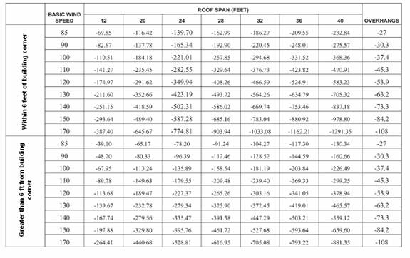
Notes:
a. The required capacities are pounds per lineal
foot of building length. For roof
framing spaced at 16 inches on center multiply table values by 1.33. For roof framing spaced at 24 inches on
center multiply table values by 2.
b. The required capacities include an allowance
for 10 pounds of dead load.
c. The required capacities do not account for
the effects of overhangs. The overhang
loads given shall be multiplied by the overhang projection and added to the required
capacities in the table.
Ray
Burroughs’ Comment:
Section 101.4, if gable end bracing is voluntary as you
indicated, this section needs to better indicate such. As written the retrofit is required as a part
of a project involving “construction which otherwise requires a permit”. Thus
if they are doing any type of activity requiring a permit it would trigger
gable wind bracing for example replacing their air conditioner, replacing their
elect panel, etc.
Mike
Moore’s Comment:
101.5 When a home inspector inspects an existing home as
part of a real estate transaction and determines that the roof decking
attachment does not meet the requirements of Section 201.1, adhesives shall be
used to strengthen the decking attachment per Section 201.2, unless the roof is
being replaced per Section 101.1.
FRSA Comment:
Replace language with the following:
201.1
Roof sheathing fastening for site-built single family residential structures. Roof sheathing shall be fastened to meet the
requirements of chapters 16 and 23 of the
Add the following to chapter 15:
1510.1.1
Roof sheathing shall be fastened to meet the requirements of chapter 16 and 23
of the
Mike Moore’s Comment:
201.1 Roof sheathing
fastening for site-built single family residential structures during
re-roofing. For site-built single family residential
structures the fasteners and spacing required in Table 201.1 are deemed to
comply with the requirements of Section 511.5,
201.2 Roof
sheathing fastening for site-built single family residential structures prior
to re-roofing. When a home
inspection completed for a real estate transaction reveals that the roof
decking attachment does not meet the fastener requirements of Table 201.1, and
when this roof will not be re-roofed at the time of the transaction, an AFG-01
approved adhesive shall be applied in a ¼” bead to the 90-degree joint between
the underside of the roof decking and the supporting roof framing to strengthen
this connection.
FRSA Comment:
201.2 Roof
secondary water barrier for site-built single family residential structures. A secondary water barrier shall be installed
using one of the following methods when roofing replacement when
reproofing, and all materials used must
meet the requirements of FBC’s product approval system for wind driven rain and
wind uplift resistance.
a) All joints in roof
sheathing or decking shall be covered with a minimum 4 in. wide strip of adhered approved membrane self-adhering
polymer modified bitumen tape applied directly to the sheathing or
decking. The deck and self adhering
polymer modified bitumen tape shall be covered with one of the underlayment
systems approved for the particular roof covering to be applied to the roof.
b) The entire roof deck
shall be covered with an approved adhered
membrane self-adhering polymer modified bitumen cap sheet. No additional underlayment shall be required
on top of this cap sheet for new installations.
c) The entire roof deck shall
be covered with a mechanically attached approved membrane.
d) All joints in the roof
sheathing shall be sealed with an approved sealant.
e) All joints in the roof sheathing shall be
sealed with an approved sealant; the entire roof shall then be covered with an
approved coating.
EXCEPTIONS:
An asphalt impregnated 30# felt underlayment installed with nails and
tin-tabs as required for the HVHZ and covered with either an approved
self-adhering polymer modified bitumen cap sheet or an approved cap sheet
applied using an approved hot-mop application shall be deemed to meet the
requirements for the secondary water barrier.
Bill Dumbaugh’s
Comment:
201.2 Secondary water barrier for site built single
family residential structures.
A secondary water barrier shall be installed
using one of the following methods when roofing replacement when reproofing.
- All joints in roof sheathing or decking
shall be covered with a minimum 4 in. wide strip of self-adhering polymer
modified bitumen tape applied directly to the sheathing or decking. The deck and self adhering polymer
modified bitumen tape shall be covered with one of the underlayment systems
approved for the particular roof covering to be applied to the roof.
- The entire roof deck shall be covered
with an approved self-adhering polymer modified bitumen cap sheet. No additional underlayment shall be
required on top of this cap sheet for new installations.
EXCEPTIONS:
1. In lieu of 1 and 2 above,
buildings and structures located in HVHZ with nailable decks shall be installed
in accordance with section 1518,
and 1519, which shall be deemed
to meet the requirements of a secondary
water barrier
1 A asphalt impregnated 30# felt underlayment
installed with nails and tin-tabs as required for the HVHZ and covered with
either an approved self-adhering polymer modified bitumen cap sheet or an
approved cap sheet applied using an approved hot-mop application shall be
deemed to meet the requirements for the secondary water barrier.
2. A roof deck that is
sufficiently fastened as prescribed in Section 201.1 and provided with a
secondary water barrier as outlined above shall be deemed to meet the
requirements of this section.
Chris Schulte’s
comments.
Ray Burroughs
Comment:
Table 201.3, last column headered “overhangs”, is this
for all overhang projections, obviously a 12 inch overhang has less uplift than
a 24 inch overhang.
General Comments:
Robert Bullard’s
Comments:
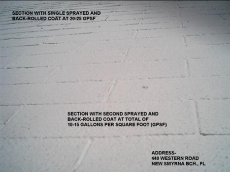
Our sister firm, Preservation Possibilities, Inc., uses
a custom latex elastomeric coating material manufactured in the USA to anchor
existing asphalt shingle roofs against being stripped off by high winds. The attached annotated photo shows two side
by side comparisons: the less dense
coating provides moderate wind-stripping resistance, the more dense will
restrain the roofing to the extent that the original nails will hold the
shingles themselves to the roof deck with no wind-peeling whatsoever for the
life of the coating.
The coating is spray-applied to weathered roofs
(shingles over five years old), with spray-jet challenging 100 per cent of the
down slope flaps of the shingles (except those at the extreme edge of the
roof), so that a significant amount of material extends up under the leading
edge of the shingles to act as an adhesive.
The less dense coating is a single layer spray application which is
back-rolled with minimal membrane development over the leading edge. This application is intended for moderate enhancement
of wind up-lift resistance of shingles; its main benefit is that by applying
the special mildew-resistant white coating, there is at least a twenty per cent
reduction in the energy bill of a typical single-story centrally-cooled
As the coating weathers free of leaf deposition, the
efficiency of the coating declines to about one-half of its original benefit at
ten years, at which point a thin 50 square feet per gallon top coat can be
applied to restore the energy efficiency.
The more dense application is achieved by applying a
second coating to create and intact membrane over the leading edge of the
shingles. If the original roofing was
properly nailed (e. g., at least 6, 6d or larger per architectural shingle
profile), a shingle roof with this coating is virtually unstrippable by wind,
except for, perhaps, the first row of shingles at the edge strip. (With respect
to anchoring the edge, at a single project site, we have have achieved robust
anchorage by pneumatically-driven pairs of “X” pattern monel staples through
the edge flaps and the metal drip edge under the flap in the perimeter of the
roof overhang; there were three clusters (pairs) per architectural shingle. At
this particular site (oceanfront) we have yet to coat because the shingles are
still too “fresh” with asphalt solvents which can potentially impair the bond
and chemical properties of the coating material.)
Present installed cost for the two-coat system is no
more than the cost of the least expensive asphalt shingle replacement roof, a
product which will not have nearly the energy efficiency or wind resistance of
the two-coat roof.
Present installed
cost for the two-coat system is no more than the cost of the least expensive
asphalt shingle replacement roof, a product which will not have nearly the
energy efficiency or wind resistance of the two-coat roof.
This coating system is a win-win for aged asphalt shingle roofs which do not have advanced deterioration problems (leaks, corrosion of flashings, rotten wood, etc.). (If there are leaks without structural consequences, these can usually be cured with the two-coat system, or, if around roof penetrations, such as vents, skylights, chimneys, etc. with multiple stripe coats during the original coating or subsequently.) With a top coating every ten years at about half the cost of the original two-coat roof, such a roofing system lasts forever. It should be part of the arsenal of the My Florida Safe Home concept.