The
following is a proposed code change to incorporate the provisions of Rule
9B-3.0475, Hurricane Mitigation Retrofits for Existing Site-Built Single Family
Residential Structures into the 2007
Revise Chapter 2, Definition, to add a definition for the term “Site Built single – family residential structures” to read as follows:
Site built single- family residential structures. This term shall mean site built single family detached residential structures
Revise Chapter 6, Alteration –Level 1, to add a new section 611.7 to read as follows:
611.7 101.1 When a roof covering on an existing
site-built - single family residential structure is removed and replaced,
the following procedures shall be permitted to be performed by the roofing
contractor:
(a) Roof-decking attachment and fasteners shall be
strengthened and corrected as required by Section 611.7.1 201.1.
(b) A secondary water barrier shall
be provided as required by section 611.7.2 201.2.
Exception: Single family residential structures
permitted subject to the Rule
section.
611.7.1 201.1 Roof decking sheathing
fastening for site-built
single family residential structures. For site-built
single family residential structures the fasteners
and spacing required in Table 201.1 are deemed to comply with the requirements
of Section 507.2.2, of the 2004
Fastening shall be in accordance with
section 611.7.1.1 201.1.1 or 611.7.1.2 201.1.2. as appropriate for
the existing construction. 8d nails shall be a minimum of 0.141 inch in
diameter and shall be a minimum of 2-1/4 inch long to qualify for the
provisions of this section for existing nails regardless of head shape or head
diameter.
Board roof
decking secured with at least two 8d nails into roof framing members shall be
deemed to be sufficiently connected.
Board roof decking secured with smaller fasteners than 8d nails or with
fewer than two 8d nails per board shall be deemed sufficiently connected if two
8d clipped head, round head, or ring shank nails are in place on each framing
member.
611.7.1.1 201.1.1 Roof decking consisting of sawn
lumber or wood planks up to 12” wide and secured with at least two nails
(minimum size 8d) to each roof framing member it crosses shall be deemed to be
sufficiently connected. Sawn lumber or
wood plank decking secured with smaller
fasteners than 8d nails or with fewer than two nails (minimum size 8d) to each
framing member it crosses shall be deemed sufficiently connected if fasteners
are added such that two clipped head, round head, or ring shank nails (minimum
size 8d) are in place on each framing member it crosses.
611.7.1.2 201.1.2 For roof decking consisting of wood
structural panels, fasteners and spacing required in columns 3 and 4 of Table 611.7.1.2
201.1.2 are deemed to comply with the requirements of Section 606.3 507.2.2,
507.2.2,
Supplemental fasteners as required by Table 611.7.1.2 201.1.2 shall be 8d ring shank nails
with round heads and the following minimum dimensions:
1. 0.113-inch nominal shank diameter
2. Ring diameter a minimum of 0.012-inch greater than over shank diameter
3. 16 to 20 rings per inch
4. a minimum 0.280-inch full
round head diameter
5. Ring shank to extend a minimum of 1 ½” from the tip of the nail.
6. Minimum 2-1/4 inch
nail length
Table 611.7.1.2 201.1
Supplement Fasteners at Panel Edges and Intermediate
Framing
|
Existing fasteners |
Existing spacing |
Wind speed 110 mph or less supplemental fastener
spacing shall be no greater than |
Wind speed greater than 110 mph supplemental
fastener spacing shall be no greater than |
|
Staples or 6d |
Any |
6” o.c. b |
6” o.c. b |
|
8d clipped head, round
head, smooth or ring shank |
6” o.c. or less |
None necessary |
None necessary |
|
8d clipped head |
Greater than 6” o.c. |
6” o.c.a |
6” o.c. |
|
|
|
|
|
a. Maximum spacing determined based on existing
fasteners and supplemental fasteners.
b. Maximum spacing determined based on
supplemental fasteners only.
611.7.2 201.2
Roof secondary water barrier for site-built single family residential
structures. A secondary water barrier shall be installed
using one of the following methods when roof covering is removed and
replaced: roofing replacement when reroofing.
a) All joints in structural panel roof
sheathing or decking shall be covered with a minimum 4 in. wide strip of
self-adhering polymer modified bitumen tape applied directly to the sheathing
or decking. The deck and self adhering
polymer modified bitumen tape shall be covered with one of the underlayment
systems approved for the particular roof covering to be applied to the
roof.
b) Outside the High
Velocity Hurricane Zone, tThe entire roof deck shall be
covered with an approved self-adhering polymer modified bitumen cap
sheet meeting ASTM D 1970 or an approved
self-adhereing synthetic underlaymet installed in accordance with the
manufacturer’s installation instructions. No additional underlayment shall be required
on top of this cap sheet for new installations.
c) In the HVHZ, the entire roof deck shall be
covered with an approved asphalt impregnated 30#
felt underlayment installed with nails and tin-tabs as required for the HVHZ in accordance with Sections 1518.4 of the Florida Building Code, Building or
R4402.7.2, R4402.7.3, or R4402.7.4 of the Florida Building Code, Residential. This method
shall also be acceptable
in the non-HVHZ regions of
d) In regions of Outside of the HVHZ, an
underlayment system approved for the particular roof
covering shall be applied with the following modification:
(1) For roof slopes that require one layer
of underlayment, complying with section 1507.2.3 of the Florida Building Code,
Building fastened as described below or a layer of approved asphalt impregnated approved ASTM D 226 Type I or Type II (#30) felt underlayment
or approved synthetic underlayment shall be installed. The felt or
synthetic underlayment is to be fastened with 1” round plastic cap or metal
cap nails, attached to a nailable deck in a grid pattern of 12 inches (305 mm)
staggered between the overlaps, with 6-inch (152 mm) spacing at the
overlaps. The
synthetic underlayment shall be fastened in accordance with the manufacturer’s
recommendations.
(2) For roof
slopes that require two layers of underlayment, an
approved asphalt impregnated ASTM D 226 Type I or Type II (#30)
underlayment of 2:12 to 4:12 an additional layer of felt shall
be installed in a shingle-fashion and lapped 19” and fastened as described
above. An approved synthetic underlayment shall be installed in accordance with
the manufacturer’s installation instruction. (No additional underlayment shall be required over the top of this
sheet).
e)
Application of a two-part urethane based closed cell spray-on adhesive to the
attic side of the joints between the sheathing and along both sides of the
truss top chords or rafters shall be deemed to meet the requirements for
the secondary water barrier.
Exceptions:
1. Roof slopes < 2:12 having a continuous roof system shall be deemed
to comply with section 201.2 requirements for a secondary water barrier.
2. Clay and Concrete tile roof systems installed as required by the
Exceptions:
1. Roof slopes < 2:12 having a continuous roof system shall be deemed
to comply with section 611.7.2 201.2 requirements for a secondary water
barrier.
2. Clay and Concrete tile roof systems installed as required by the 201.2 for
Secondary Water Barriers.
1. An asphalt impregnated 30# felt underlayment
installed with nails and tin-tabs as required for the HVHZ and covered with
either an approved self-adhering polymer modified bitumen cap sheet or an
approved cap sheet applied using an approved hot-mop application shall be
deemed to meet the requirements for the secondary water barrier.
611.8 101.2 When a roof covering
on an existing site-built-single-family residential structure is removed and replaced on a building that is located
in the wind-borne debris region as defined in s. 1609.2 of the
(a) Roof to wall
connections shall be improved as required by Section 611.8.1 201.3.
(b) Mandated retrofits of the roof-to-wall
connection shall not be required beyond a 15 percent increase in the cost of
re-roofing.
(c) Where
complete retrofits of all the roof-to-wall connections as prescribed in Section
611.8.1 201.3 would exceed 15 percent of the cost of the
re-roofing project, the priorities outlined in Section 611.8.1.7 201.3.75
shall be used to limit the scope of work to the 15 percent limit.
Exception: Single family
residential structures permitted subject to the Rule section.
201.3 611.8.1 Roof-to-wall
connections for site-built
single family residential structures. Where
required by Section 611.8 101.2, the intersection of roof framing
with the wall below shall be strengthened by adding metal connectors, clips,
straps, and fasteners such that the performance level equals or exceeds the
uplift capacities as provide sufficient resistance to meet the uplift
loads specified in Table 611.8.1 201.3 either because of
existing conditions or through retrofit measures. As an alternative to an
engineered design, the prescriptive retrofit solutions provided in Sections 611.8.1.1
201.3.12 through 611.8.1.6 201.3.45 shall be
accepted as meeting the mandated roof-to-wall retrofit requirements.
Exceptions:
1. Where it can be demonstrated
(by code adoption date documentation and permit issuance date) that
roof-to-wall connections and/or roof-to-foundation continuous load path
requirements were required at the time of original construction.
2. Roof- to- wall
connections shall not be required unless evaluation and installation of
connections at gable ends or all corners can be completed for 15% of the cost
of roof replacement.
611.8.1.1 201.3.1 Access for
Retrofitting Roof to Wall Connections. These provisions are not intended to limit
the means for gaining access to the structural elements of the roof and wall
for the purposes of retrofitting the connection. The retrofit of roof to wall connections can be made by access through
the area under the eave, from above through the roof, or from the interior of
the house. Methods for above access
include removal of roof panels or sections thereof or removal of portions of
roof paneling at selected locations large enough for access, viewing, and installing
the retrofit connectors and fasteners.
Where panels or
sections are removed, the removed portions shall not be reused. New paneling shall be used and fastened as in
new construction.
Holes shall be deemed adequately repaired if a patch of
paneling is installed with no gap greater than ½ inch between the patch and the
existing sheathing and if the patch is supported using one of the following
methods.
a) Solid 1-1/2 inch lumber
shall fully support the patch and shall be secured to the existing sheathing
with #8 by 1-1/4 inch screws spaced a minimum of 3” around the perimeter with
screws a minimum of ¾ inch from the near edge of the hole. The patch shall be secured to the lumber with
#8 x 1-1/4 inch screws spaced on a grid no greater than 6 inches by 6 inches
with no fewer than 2 screws.
b) Holes that extend
horizontally from roof framing member to adjacent roofing framing member that
are less than or equal to 7” wide along the slope of the roof shall be supported by minimum of 2x4 lumber
whose face is attached to each roofing framing members using a minimum of 2
each 3-inch long fasteners (#8 screws or
10d common nails) connecting the two.
The patch shall have attached to its bottom running horizontally a
minimum 2x4 either flat wise or on edge secured with #8 x 1-1/4 inch screws a
maximum of 4 inches on center and no more distant from the end of the added
lumber than 3 inches. The patch shall be
secured with two #8 x 1-1/4 inch screws to each support member.
611.8.1.2
201.3.2 Partially inaccessible straps: Where part of a strap is inaccessible, if
the portion of the strap that is observed is fastened in compliance with these
requirements, the inaccessible portion of the strap shall be presumed to comply
with these requirements.
611.8.1.3
201.3.31 Prescriptive method for gable roofs on a wood
frame wall. Sufficient eave sheathing shall be removed to
expose a minimum of 6-feet of framing members, measured from the corner, along
the exterior wall on each side of each gable end. The
anchorage of each of the exposed rafters or truss within 6 ft of the
framing members as measured from the corner along the exterior wall on
each side of each gable end shall
be inspected. Wherever a strap is
missing or an existing strap has fewer than four fasteners on each end,
approved straps, ties or right angle gusset brackets with a minimum
uplift capacity of 500 lbs shall be installed that connect each rafter or truss
to the top plate below. Adding fasteners
to existing straps shall be allowed in lieu of adding a new strap provided the
strap is manufactured to accommodate at least 4 fasteners at each end. Wherever access makes it possible (without
damage of the wall or soffit finishes), both top plate members shall be
connected to the stud below using a stud to plate connector with a minimum
uplift capacity of 500 lbs. Use of
straps that connect directly from the rafter or truss to the wall stud below
shall be allowed as an alternate provided the two members align with no more
than 1-1/2” offset.
611.8.1.4
201.3.42 Prescriptive method for gable roofs on a
masonry wall. Sufficient eave sheathing shall be removed to
expose a minimum of 6-feet of framing members, measured from the corner, along
the exterior wall on each side of each gable end. The anchorage of each of the exposed
rafters or truss within 6 ft of the framing members as
measured from the corner along the exterior wall on each side of each
gable end shall be inspected. Wherever a strap is missing or an existing
strap has fewer than four fasteners on each end, approved straps, ties or right
angle gusset brackets with a minimum uplift capacity of 500 lbs shall be
installed that connect each rafter or truss to the top plate below or directly
to the masonry wall using approved masonry screws that will provide at least a
2-1/2 embedment into the concrete or masonry.
When the straps or right angle gusset brackets are attached to a wood
sill plate, the sill plate shall be anchored to the concrete masonry wall
below. This anchorage shall be accomplished
by installing ¼-inch diameter masonry screws, each with supplementary ¼-inch
washer, having sufficient length to develop a 2-1/2 inch embedment into the
concrete and masonry. These screws shall
be installed within 4-inches of the truss or rafter on both sides of each
interior rafter or truss and on the accessible wall side of the gable end truss
or rafter.
611.8.1.5
201.3.53
Prescriptive method for hip roofs on a wood frame wall. Unless it is possible to verify through
non-destructive inspection or from plans prepared by a design professional that
the roof structure is anchored at least as well as outlined below, access
shall be provided at a minimum to the hip rafter (commonly known as a “king
jack”), to the hip girder and at each corner of the hip roof. The hip rafter (commonly known as a “king jack”), the hip girder and
the rafters/trusses adjacent to the hip girder Sufficient
corner eave sheathing shall be removed from the side of the hip ridge parallel
to the roof ridge to provide access to a minimum 6-foot length of the exterior
wall. The hip ridge board and any
exposed rafters that are not anchored with a strap having at least four
fasteners on each end, shall be connected to the top plate below using a strap
or a right angle gusset bracket having a minimum uplift capacity of 500
lbs. Adding fasteners to existing straps
shall be allowed in lieu of adding a new strap provided the strap is
manufactured to accommodate at least 4 fasteners at each end. Wherever access makes it possible (without
damage of the wall or soffit finishes), both top plate members shall be
connected to the stud below using a stud to plate connector with a minimum
uplift capacity of 500 lbs. Use of
straps that connect directly from the hip rafter, hip girder or adjacent
rafters/trusses to the wall stud below shall be allowed as an alternate
provided the two members align with no more than 1-1/2” offset.
611.8.1.6
201.3.64 Prescriptive method for hip roofs on a masonry
wall. Unless it is possible to verify through
non-destructive inspection or from plans prepared by a design professional that
the roof structure is anchored at least as well as outlined below, access
shall be provided at a minimum to the hip rafter (commonly known as a “king
jack”), to the hip girder and at each corner of the hip roof. The hip rafter (commonly known as a “king jack”), the hip girder and the rafters/trusses adjacent to the hip
girder Sufficient corner eave sheathing shall be
removed from the side of the hip ridge parallel to the roof ridge to provide
access to a minimum 6-foot length of the exterior wall. The hip ridge board and any exposed rafters
that are not anchored with a strap
having at least four fasteners on each end, shall be connected to the concrete
masonry wall below using approved straps or right angle gusset brackets with a
minimum uplift capacity of 500 lbs.
Adding fasteners to existing straps shall be allowed in lieu of adding a
new strap provided the strap is manufactured to accommodate at least 4
fasteners at each end. The straps or
right angle gusset brackets shall be installed such that they connect each
rafter or truss to the top plate below or directly to the masonry wall using
approved masonry screws that will provide at least a 2-1/2 embedment into the
concrete or masonry. When the straps or
right angle gusset brackets are attached to a wood sill plate, the sill plate
shall be anchored to the concrete masonry wall below. This anchorage shall be accomplished by
installing ¼-inch diameter masonry screws, each with supplementary ¼-inch
washer, with sufficient length to develop a 2-1/2 inch embedment into the
concrete and masonry. These screws shall
be installed within 4-inches of the truss or rafter on both sides of each
interior rafter or truss and on the accessible wall side of the gable end truss
or rafter.
611.8.1.7
201.3.65 Priorities for mandated roof-to-wall retrofit
expenditures. Priority shall be given to
connecting the exterior corners of roofs to walls where the spans of the
roofing members are greatest. For houses with both hip and gable roof ends,
the priority shall be to retrofit the gable end roof-to-wall connections unless
the width of the hip end is more than 1.5 times greater than the width of the
gable end. Priority shall be given to connecting the
corners of roofs to walls below where the spans of the roofing members are
greatest.
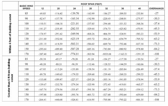
Table 611.8.1 201.3
Required
Uplift Capacities for Roof-to-Wall Connections
(POUNDS
PER LINEAR FOOT)
Chapter 1,
Administration
101.3 105.15 When any activity
requiring a building permit that is applied for on or after s. 1609.2 of the , Building and that has
an insured value of $750,000 or more, or, if the building is uninsured or for
which documentation of insured value is not presented, has a just valuation for
the structure for purposes of ad valorem taxation of $750,000 or more.
Opening protections as required within the
[ Appendix A Gable and Wall
Bracing Retrofit has been omitted and will be provided later
The Committee at
the last meeting deferred action for Richard Reynolds to provide language
necessary to incorporate the appendix as a Chapter in the Existing Building
Volume.]