101 Retrofits
Required. Pursuant to Section
553.844, Florida Statutes, strengthening of existing site-built, single family
residential structures to resist hurricanes shall be provided. Site built single-
family residential structures shall mean site built single family detached
residential structures.
101.1 When a roof on an existing site-built, single family residential structure is replaced, the following procedures shall be permitted to be performed by the roofing contractor:
(a) Roof-decking attachment and fasteners shall be strengthened and corrected as required by section 201.1.
(b) A secondary water barrier shall be provided as required by section 201.2.
101.2 When
a roof is replaced on a building that is located in the wind-borne debris
region as defined in s. 1609.2 of the
(a) Roof to wall connections shall be improved as required by section
201.3.
(b) Mandated
retrofits of the roof-to-wall connection shall not be required beyond a 15
percent increase in the cost of re-roofing.
(c) Where
complete retrofits of all the roof-to-wall connections as prescribed in Section
201.3 would exceed 15 percent of the cost of the re-roofing project, the
priorities outlined in Section 201.3.75 shall be used to limit
the scope of work to the 15 percent limit.
101.3
When any activity requiring a building permit that
is applied for on or after July 1, 2008, and for which the estimated cost is
$50,000 or more for a building that is located in the wind borne debris region
as defined in s. 1609.2 of the
(a)
Opening protections as required within the
101.4 When retrofit enhancement of gable end bracing is provided during construction which otherwise requires a permit the techniques in Appendix A shall be allowed.
201 Roof
System Mitigation Techniques. Roof
sheathing fastening, secondary water barriers, roof to wall connection and
gable end bracing shall be permitted pursuant to this section.
201.1 Roof
sheathing fastening for site-built
single family residential structures. For site-built
single family residential structures the
fasteners and spacing required in Table 201.1 are deemed to comply with the
requirements of Section 507.2.2, of the 2004
Board roof decking
secured with at least two 8d nails into roof framing members shall be deemed to
be sufficiently connected. Board roof
decking secured with smaller fasteners than 8d nails or with fewer than two 8d
nails per board shall be deemed sufficiently connected if two 8d clipped head,
round head, or ring shank nails are in place on each framing member.
Supplemental fasteners as required by Table 201.1 shall be 8d
ring shank nails with round heads and the following minimum dimensions:
1. 0.113 inch nominal shank diameter
2. Ring diameter of 0.012 over shank diameter
3. 16 to 20 rings per inch
4. 0.280 inch full round head diameter
5. Ring shank to extend a minimum of 1 ½” from the tip of
the nail.
6. Minimum 2-1/4 inch nail length
Table 201.1
Supplement Fasteners at Panel Edges and
Intermediate Framing
|
Existing fasteners |
Existing spacing |
Wind speed 110 mph or less supplemental fastening shall be no greater than |
Wind speed greater than 110 mph supplemental fastening shall be no greater than |
|
Staples or 6d |
Any |
6” o.c. b |
6” o.c. b |
|
8d clipped head,
round head, or ring shank |
6” o.c. or less |
None necessary |
None necessary |
|
8d clipped head, |
Greater than 6” o.c. |
6” o.c.a |
6” o.c. |
|
|
|
|
|
a. Maximum spacing determined based on existing
fasteners and supplemental fasteners.
b. Maximum spacing determined based on
supplemental fasteners only.
201.2 Roof
secondary water barrier for site-built single family residential structures. A secondary water barrier shall be installed
using one of the following methods when roofing replacement when
reroofing.
a) All joints in structural panel roof
sheathing or decking shall be covered with a minimum 4 in. wide strip of
self-adhering polymer modified bitumen tape applied directly to the sheathing
or decking. The deck and self adhering
polymer modified bitumen tape shall be covered with one of the underlayment
systems approved for the particular roof covering to be applied to the roof.
b) The entire roof deck shall be covered with an
approved self-adhering polymer modified bitumen cap sheet. No additional underlayment shall be required
on top of this cap sheet for new installations.
c) The
entire roof deck shall be covered with an approved asphalt impregnated 30# felt
underlayment installed with nails and tin-tabs as required for the HVHZ. (No additional underlayment shall be required over the top
of this sheet).
d) Outside of the HVHZ, an underlayment complying with section 1507.2.3 of the
Florida Building Code, Building fastened as described below or a
layer of asphalt impregnated approved #30 felt
shall be installed. The felt is to be fastened with 1” round plastic cap or
metal cap nails, attached to a nailable deck in a grid pattern of 12 inches
(305 mm) staggered between the overlaps, with 6-inch (152 mm) spacing at the
overlaps. For slopes of 2:12 to 4:12 an
additional layer of felt shall be installed in a shingle-fashion and lapped 19”
and fastened as described above. (No additional underlayment shall be required over the top of this
sheet).
Exceptions:
1. Roof slopes < 2:12 having a continuous roof system shall be deemed
to comply with section 201.2 requirements for a secondary water barrier.
2. Clay and Concrete tile roof systems installed as required by the
1. An asphalt impregnated 30# felt underlayment installed with nails and
tin-tabs as required for the HVHZ and covered with either an approved
self-adhering polymer modified bitumen cap sheet or an approved cap sheet
applied using an approved hot-mop application shall be deemed to meet the
requirements for the secondary water barrier.
201.3 Roof-to-wall connections for site-built single family residential structures. Where
required by Section 101.2, the intersection of roof framing with the wall below
shall be strengthened by adding metal connectors, clips, straps, and fasteners
such that the performance level equals or exceeds the uplift capacities as
specified in Table 201.3. As an
alternative to an engineered design, the prescriptive retrofit solutions
provided in Sections 201.3.31 through 201.3.64
shall be accepted as meeting the mandated roof-to-wall retrofit requirements.
Exceptions:
1. Where it can be demonstrated (by code
adoption date documentation and permit issuance date) that roof-to-wall
connections and/or roof-to-foundation continuous load path requirements were
required at the time of original construction.
2. Roof- to- wall
connections shall not be required unless evaluation and installation of
connections at gable ends or all corners can be completed for 15% of the cost
of roof replacement.
201.3.1 Access for Retrofitting Roof to Wall
Connections. These provisions are not intended to limit
the means for gaining access to the structural elements of the roof and wall
for the purposes of retrofitting the connection. The retrofit of roof to wall connections can be made by access through
the area under the eave, from above through the roof, or from the interior of
the house. Methods for above access
include removal of roof panels or sections thereof or removal of portions of
roof paneling at selected locations large enough for access, viewing, and
installing the retrofit connectors and fasteners.
Where panels or
sections are removed, the removed portions shall not be reused. New paneling shall be used and fastened as in
new construction.
201.3.2 Partially inaccessible straps: Where part of a strap is inaccessible, if
the portion of the strap that is observed is fastened in compliance with these
requirements, the inaccessible portion of the strap shall be presumed to comply
with these requirements.
201.3.31 Prescriptive method
for gable roofs on a wood frame wall. Sufficient eave sheathing shall be removed to
expose a minimum of 6-feet of framing members, measured from the corner, along
the exterior wall on each side of each gable end. The
anchorage of each of the exposed rafters or truss within 6 ft of the
framing members as measured from the
corner along the exterior wall on each side of each gable end shall be inspected. Wherever a strap is missing or an existing
strap has fewer than four fasteners on each end, approved straps, ties or right
angle gusset brackets with a minimum uplift capacity of 500 lbs shall be
installed that connect each rafter or truss to the top plate below. Adding fasteners to existing straps shall be
allowed in lieu of adding a new strap provided the strap is manufactured to
accommodate at least 4 fasteners at each end.
Wherever access makes it possible (without damage of the wall or soffit
finishes), both top plate members shall be connected to the stud below using a
stud to plate connector with a minimum uplift capacity of 500 lbs.
201.3.42 Prescriptive method
for gable roofs on a masonry wall. Sufficient eave sheathing shall be removed to
expose a minimum of 6-feet of framing members, measured from the corner, along
the exterior wall on each side of each gable end. The
anchorage of each of the exposed rafters or truss within 6 ft of the
framing members as measured from the
corner along the exterior wall on each side of each gable end shall be inspected. Wherever a strap is missing or an existing
strap has fewer than four fasteners on each end, approved straps, ties or right
angle gusset brackets with a minimum uplift capacity of 500 lbs shall be
installed that connect each rafter or truss to the top plate below or directly
to the masonry wall using approved masonry screws that will provide at least a
2-1/2 embedment into the concrete or masonry.
When the straps or right angle gusset brackets are attached to a wood
sill plate, the sill plate shall be anchored to the concrete masonry wall
below. This anchorage shall be
accomplished by installing ¼-inch diameter masonry screws, each with
supplementary ¼-inch washer, having sufficient length to develop a 2-1/2 inch
embedment into the concrete and masonry.
These screws shall be installed within 4-inches of the truss or rafter
on both sides of each interior rafter or truss and on the accessible wall side
of the gable end truss or rafter.
201.3.53 Prescriptive method
for hip roofs on a wood frame wall. Unless it is possible to verify through
non-destructive inspection or from plans prepared by a design professional that
the roof structure is anchored at least as well as outlined below, access shall be provided at a minimum to the hip rafter (commonly known as a “king jack”), to the hip girder and at each
corner of the hip roof. The hip rafter (commonly known as a “king jack”), the hip girder and the
rafters/trusses adjacent to the hip girder Sufficient corner eave
sheathing shall be removed from the side of the hip ridge parallel to the roof
ridge to provide access to a minimum 6-foot length of the exterior wall. The hip ridge board and any exposed rafters
that are not anchored with a strap having at least four fasteners on each end,
shall be connected to the top plate below using a strap or a right angle gusset
bracket having a minimum uplift capacity of 500 lbs. Adding fasteners to existing straps shall be
allowed in lieu of adding a new strap provided the strap is manufactured to
accommodate at least 4 fasteners at each end.
Wherever access makes it possible (without damage of the wall or soffit
finishes), both top plate members shall be connected to the stud below using a
stud to plate connector with a minimum uplift capacity of 500 lbs.
201.3.64 Prescriptive method for hip roofs on a masonry
wall. Unless it is
possible to verify through non-destructive inspection or from plans prepared by
a design professional that the roof structure is anchored at least as well as
outlined below, access shall be provided
at a minimum to the hip rafter (commonly known as a “king jack”), to the hip girder and at each
corner of the hip roof. The hip rafter (commonly known as a “king jack”), the hip girder and the
rafters/trusses adjacent to the hip girder Sufficient corner eave
sheathing shall be removed from the side of the hip ridge parallel to the roof
ridge to provide access to a minimum 6-foot length of the exterior wall. The hip ridge board and any exposed rafters
that are not anchored with a strap having at least four fasteners on each end,
shall be connected to the concrete masonry wall below using approved straps or
right angle gusset brackets with a minimum uplift capacity of 500 lbs. Adding fasteners to existing straps shall be
allowed in lieu of adding a new strap provided the strap is manufactured to
accommodate at least 4 fasteners at each end.
The straps or right angle gusset brackets shall be installed such that
they connect each rafter or truss to the top plate below or directly to the
masonry wall using approved masonry screws that will provide at least a 2-1/2
embedment into the concrete or masonry.
When the straps or right angle gusset brackets are attached to a wood
sill plate, the sill plate shall be anchored to the concrete masonry wall
below. This anchorage shall be
accomplished by installing ¼-inch diameter masonry screws, each with
supplementary ¼-inch washer, with sufficient length to develop a 2-1/2 inch
embedment into the concrete and masonry.
These screws shall be installed within 4-inches of the truss or rafter
on both sides of each interior rafter or truss and on the accessible wall side
of the gable end truss or rafter.
201.3.75 Priorities for
mandated roof-to-wall retrofit expenditures.
For houses with both hip and gable roof ends, the priority shall be to
retrofit the gable end roof-to-wall connections unless the width of the hip end
is more than 1.5 times greater than the width of the gable end. Priority shall be given to connecting the corners
of roofs to walls below where the spans of the roofing members are greatest.
Table 201.3
Required
Uplift Capacities for Roof-to-Wall Connections
(POUNDS
PER LINEAR FOOT)
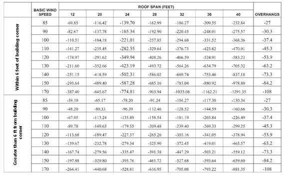
Notes:
a. The required capacities are pounds per lineal
foot of building length. For roof
framing spaced at 16 inches on center multiply table values by 1.33. For roof framing spaced at 24 inches on
center multiply table values by 2.
b. The required capacities include an allowance
for 10 pounds of dead load.
c. The required capacities do not account for
the effects of overhangs. The overhang
loads given shall be multiplied by the overhang projection and added to the
required capacities in the table.
APPENDIX A
GABLE END WALL BRACING RETROFIT
SECTION
A101
GENERAL
A101.1 Intent and purpose. The provisions of this subsection provide prescriptive solutions for
the retrofitting of gable ends of buildings. The retrofit measures are not
intended to provide strengthening of buildings equal to the structural
provisions of the latest building code requirements for new buildings. Design for compliance of new buildings and
additions to existing buildings shall conform to the requirements of the
A101.2 Scope.
The following prescriptive
methods are intended for applications where the gable end wall framing is
provided by a wood gable end wall truss or a conventionally framed rafter
system. The retrofits are appropriate
for wall studs oriented with their broad face parallel to or perpendicular to
the gable wall surface. An overview
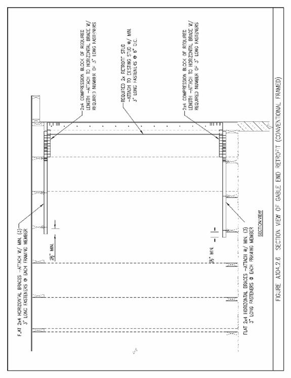
perspective drawing of the retrofit is shown in Figure A104.1.
SECTION A102
DEFINITIONS
ANCHOR BLOCK. A nominal 2-inch thick by at least 4” wide piece of lumber
secured to horizontal braces and filling the gap between existing framing
members for the purpose of restraining horizontal braces from movement
perpendicular to the framing members.
COMPRESSION
BLOCK. A nominal 2-inch thick by at least 4” wide piece of lumber used to restrain in the
compression mode (force directed towards the interior of the attic) an existing
or retrofit stud. It is attached to a
horizontal brace and bears directly against the existing or retrofit stud.
CONVENTIONALLY
FRAMED GABLE END. A conventionally framed gable end with studs
whose faces are perpendicular to the gable end wall.
HORIZONTAL BRACE. A
nominal 2-inch thick by at least 4”
wide piece of lumber used to restrain both compression and tension loads
applied by a retrofit stud. It is
typically installed horizontally on the top of floor framing members (truss
bottom chords or ceiling joists) or on the bottom of pitched roof framing
members (truss top chord or rafters).
RETROFIT STUD. A
nominal 2-inch lumber member used to structurally supplement an existing gable
end wall stud.
RIGHT ANGLE GUSSET BRACKET. A 14
gage or thicker metal right angle bracket with a minimum load capacity
perpendicular to the plane of either face of 350 lbs when connected to wood or
concrete with manufacturer specified connectors.
STUD-TO-PLATE CONNECTOR. A
manufactured metal connector designed to connect studs to plates with a minimum
uplift capacity of 500 lbs.
TRUSS GABLE END. An
engineered factory made truss or site built truss that incorporates factory
installed or field installed vertical studs with their faces parallel to the
plane of the truss and are spaced no greater than 24-inches on center. Web or other diagonal members other than top
chords may or may not be present. Gable
end trusses may be of the same height as nearby trusses or may be drop chord
trusses in which the top chord of the truss is lower by the depth of the top
chord or outlookers.
SECTION A103
MATERIALS OF CONSTRUCTION
A103.1 Existing materials. All existing wood materials
that will be part of the retrofitting work (trusses, rafters, ceiling joists,
top plates, wall studs, etc.) shall be in sound condition and free from defects
or damage that substantially reduce the load-carrying capacity of the
member. Any wood materials found to be
damaged or deteriorated shall be strengthened or replaced with new materials to
provide a net dimension of sound wood equivalent to its undamaged original
dimensions.
A103.2
New Materials. All materials approved by this
code, including their appropriate allowable stresses, shall be permitted to
meet the requirements of this chapter.
A103.3 Dimensional Lumber. All dimensional lumber for braces, studs, and
blocking shall conform to applicable standards or grading rules. Dimensional lumber shall be identified by a
grade mark of a lumber grading or inspection agency that has been approved by
an accreditation body that complies with DOC PS 20. All new dimensional lumber to be used for
retrofitting purposes shall be a minimum grade and species of #2 Spruce-Pine-Fir
or shall have a specific gravity of 0.42 or greater. In lieu of a grade mark, a certificate of
inspection issued by a lumber grading or inspection agency meeting the
requirements of this code shall be accepted.
A103.4 Metal Plate Connectors,
Straps and Anchors. Metal plate
connectors, straps and anchors shall have product approval. They shall be approved for connecting
wood-to-wood or wood-to-concrete as appropriate. Straps
and tie plates shall be manufactured from galvanized steel with a minimum thickness
provided by 20 gauge. Tie plates shall
have holes sized for 8d nails.
A103.5 Twists in
straps. Straps shall be permitted to be
twisted 90 degrees in addition to a 90 degree bend where they transition
between framing members or connection points.
A103.6 Fasteners. Fasteners meeting the requirements of
Sections A103.6.1 and A103.6.2 shall be used and shall be permitted to be
screws or nails meeting the minimum length requirement shown in figures and
specified in tables.
A103.6.1 Screws. Screws shall be a minimum #8 size with head diameters no less than 0.3 inch. Screw lengths shall be no less than
indicated in the Figures and in Tables. Permissible screws include deck
screws, wood screws, or sheet metal screws (without drill bit type tip, but can
be sharp pointed). Screws shall have at
least 1 inch of thread. Fine threaded
screws or drywall screws shall not be permitted. Note that many straps will not accommodate
screws larger than #8.
A103.6.2 Nails. Unless otherwise indicated in the provisions
or drawings, where fastener lengths are indicated in Figures and Tables as 1-¼ inch, 8d common nails with shank diameter 0.131 inch and head
diameters no less than 0.3 inch shall be permitted. Unless otherwise indicated in the provisions
or drawings, where fasteners lengths are indicated in Figures and Tables
as 3 inch, 10d common nails with shank
diameter of 0.148 inch and head diameters no less than 0.3 inch shall be
permitted.
A103.7 Fastener
spacing. Fastener spacing shall be as
follows:
a) distance between fasteners and the edge of lumber shall be a minimum of ½ inch
unless otherwise indicated,
b) distance between fasteners and the end of lumber shall be a minimum of
2-½ inch,
c) distance between fasteners
parallel to grain (center-to-center) when straps are not used shall be a
minimum of 2-1/2 inches unless a ½-inch stagger (perpendicular to the grain) is
applied for adjacent fasteners, then the distance between fasteners parallel to
the grain shall be a minimum of 1-1/4 inches.
d). distance between fasteners across grain (row spacing) when straps
are not used shall be a minimum of 1 inch, and the
e) distance between fasteners inserted in metal plate connectors,
straps and anchors as defined in Section A103.4 shall be those provided by
holes manufactured into the straps.
SECTION A104
RETROFITTING GABLE END WALLS
A104.1 Scope and intent. Gable
ends to be strengthened shall be permitted to be retrofitted using methods
prescribed by provisions of this section.
These prescriptive methods of retrofitting are intended to increase the
resistance of existing gable end wall construction for out-of-plane wind loads
resulting from high wind events. The
retrofit method addresses four issues.
These include strengthening the framing members of the walls if
necessary (retrofit studs), bracing the top and bottom of the gable wall so
that lateral loads are transmitted into the roof and ceiling diaphragms
(horizontal braces, straps to retrofit studs and compression blocks) and
connecting the bottom of the gable end wall to the wall below to help brace the
top of that wall (specialty metal brackets).
The following prescriptive methods are intended for applications where
the gable end wall framing is provided by a wood gable end wall truss or a
conventionally framed rafter system. The
retrofits are appropriate for wall studs oriented with their broad face
parallel to or perpendicular to the gable wall surface. An overview perspective drawing of the
retrofit is shown in Figure A104.1.
A104.2 Horizontal Braces.
Horizontal braces shall be installed approximately perpendicular to the
top and bottom chords of the existing roof trusses or approximately
perpendicular to the rafters and ceiling joists at the location of each existing
gable end wall stud greater than 3-feet in length. If the spacing of existing gable end studs is
greater than 24 inches or no vertical gable end stud is present, a stud and
horizontal braces shall be installed such that the maximum spacing between
existing and added studs shall be 24–inches.
Additional gable end wall studs shall not be required at locations where
their length would be 3-feet or less.
Each required added stud shall be attached to the existing roofing
framing members (truss top chord or rafter and truss bottom chord or ceiling
joist) using a minimum of two 3-inch toenail fasteners (#8 wood screws or 10d
nails) and a metal connector or mending plate with a minimum of four 1-1/4 inch
long fasteners (#8 wood screws or 8d nails) at each end. The horizontal braces shall consist of the
minimum size member indicated in Table A104.2.
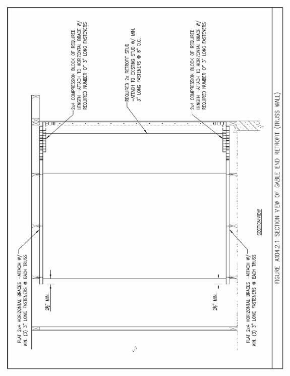
The horizontal brace shall be oriented with their long face across the
top and bottom chords of the wood trusses (or rafters and ceiling joists) and
extend a minimum of three framing spacings from the gable end wall plus 2-1/2
inch beyond the last top chord or bottom chord member (rafter or ceiling joist)
as shown in Figure A104.2.1 (and A104.2.6).
The horizontal brace shall be located no farther than 1/2
inch from the inside face of the gable end wall truss. Each horizontal brace shall be fastened to
each existing framing member (top chord or rafter or bottom chord or ceiling
joist) that it crosses using three 3-inch long fasteners (#8 wood screws or 10d
nails) as indicated in Figures A104.2.2 through A104.2.5 for trusses (and
Figures A104.2.7 through A104.2.10 for rafters).
Exceptions:
1. Where obstructions, other permanently attached obstacles or
conditions exist that will not permit installation of new horizontal braces at
the indicated locations, refer to Section A104.5 for permitted modification of
these prescriptive retrofit methods.
2. Where obstructions, other permanently attached obstacles or
conditions exist that will not permit extension of the new horizontal braces across
the existing framing members a minimum of three framing spaces from the gable
end wall, the horizontal braces may be shortened provided that all of the
following conditions are met.
a. The horizontal brace shall be installed across a minimum of two
framing spaces and fastened to each existing framing member with three 3-inch
long fasteners (#8 wood screws or 10d nails).
b. The minimum size of the anchor block shall be equivalent to the
existing framing members. The anchor
block shall be fastened to the side of the horizontal brace in the second
framing space from the gable end wall as shown in Figure A104.2.11. Six 3-inch long fasteners (#8 wood screws or
10d nails) shall be used to fasten the anchor block to the side of the
horizontal brace.
c. The anchor block shall extend beyond the surface of the horizontal
brace that is in contact with the existing framing members a minimum of
one-half the depth of the existing framing member. The anchor block shall be installed tightly
between the existing framing members such that the gap at either end shall not
exceed 1/8 inch.
A104.3 Retrofit Studs. The
retrofit studs shall consist of the minimum size members for the height ranges
of the existing vertical gable end wall studs indicated in Table A104.2. Retrofit studs shall be installed adjacent to
the existing or added (Section A104.2) vertical gable end wall studs and extend
from the top of the lower horizontal brace to the bottom of the upper
horizontal brace. A maximum gap of
1/8-inch shall be permitted between the retrofit stud and the bottom horizontal
brace. A maximum gap of 1/2-inch shall
be permitted between the top edge of the retrofit stud closest to the upper
horizontal brace and the horizontal brace surface.
Exception:
Where obstructions, other permanently attached obstacles or conditions
exist that will not permit the installation of a new retrofit stud adjacent to
an existing gable end wall stud, refer to Section A104.5 for permitted
modification of these prescriptive retrofit methods.
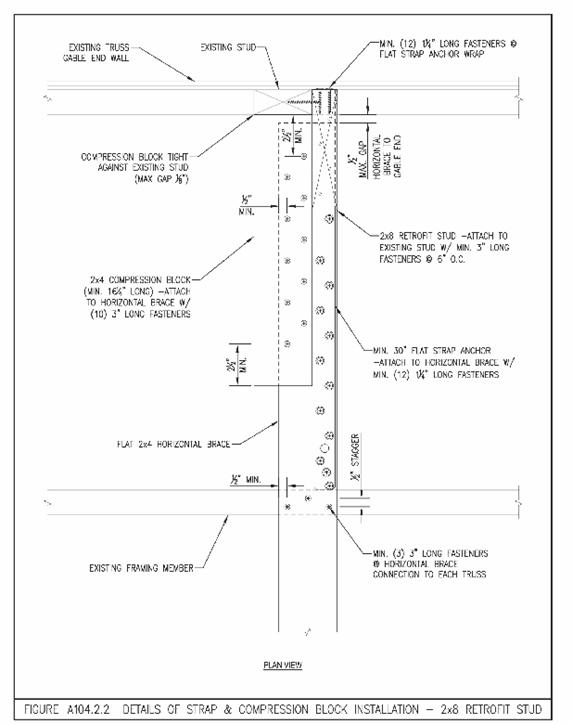
A104.3.1 Retrofit Stud Fastening. Each
retrofit stud shall be fastened to the top and bottom horizontal brace members
with a minimum of a 20 gauge, 11/4 inch wide flat metal
strap with pre-punched fastener holes.
The flat metal straps shall be the minimum length as indicated in Table
A104.2. Each top and bottom strap shall
extend sufficient distance onto the vertical face of the retrofit stud and be
fastened with the number of 1-1/4 inch long fasteners (#8 wood screws or 8d
nails) indicated in Table A104.2. Each
strap shall be fastened to the top and bottom horizontal brace members with the
minimum number of 1-1/4 inch long fasteners (#8 wood screws or 8d nails) as
indicated in Table A104.2. The retrofit
stud members shall also be fastened to the side of the existing vertical gable
end wall studs with 3-inch long fasteners (#8 wood screws or 10d nails) spaced
at 6-inches on center as shown in Figure A104.2.1.
A104.3.2 Retrofit Stud Splices.
Retrofit studs greater than 8-feet in height may be field spliced as
shown in Figure A104.3.
A104.4 Compression Blocks.
Compression blocks shall have minimum lengths as indicated in Table
A104.2. Compression blocks shall be
installed on the horizontal braces directly against either the existing
vertical gable end wall stud or the retrofit stud. For clarity, Figures A104.2.2 through
A104.2.5 (trusses) and Figures A104.2.7 through A104.2.10 (rafters) show the
installation of the compression block against the existing vertical gable end
wall stud with the strap from the retrofit stud running beside the compression
block. When the compression block is
installed against the retrofit stud, the block shall be allowed to be placed on
top of the strap. A maximum gap between
the compression block and the existing vertical gable end wall stud member or
retrofit stud of 1/8 inch shall be permitted. Compression blocks shall be fastened to the
horizontal braces with the minimum number of 3-inch long fasteners (#8 wood
screws or 10d nails). End and edge distances for fastener installation shall be
as listed in Section A103.7 and shown in Figures A104.2.2 through A104.2.5
(trusses) and Figures A104.2.7 through A104.2.10 (rafters).
A104.5
Obstructions – Permissible modifications to prescriptive gable end retrofits. Where obstructions, other permanently attached obstacles or conditions exist in attics that preclude the
installation of a retrofit stud or horizontal braces in accordance with
Sections A104.2 or A104.3, the gable end retrofit shall be deemed to meet the
requirements of this section if the requirements of Section A104.5.1 are
met. Obstructions to the installation of
retrofit studs or horizontal braces include gable end vents, attic accesses,
recessed lights, skylight shafts, chimneys, air conditioning ducts, or equipment. Where the installation of a horizontal brace
for the top of a center stud is obstructed by truss plates near the roof peak,
methods prescribed in A104.5.1 are permitted to be used, or retrofit ridge ties
as prescribed in Section A104.5.2 are permitted to be used to support the
horizontal brace.
A104.5.1 Remedial
measures where obstacles prevent installation of retrofit studs or horizontal
braces. If a retrofit stud or horizontal
brace cannot be installed because of an obstruction, the entire assembly can be
omitted from that location provided all of the following conditions are met.
1. No more than two assemblies of retrofit studs and
horizontal braces are omitted on a single gable end.
2. There shall be at least two retrofit studs and
horizontal brace assemblies on either side of the locations where the retrofit
studs and horizontal bracing members are omitted (no two ladder braces bearing
on a single retrofit stud).
3. The retrofit studs on each side of the omitted
retrofit stud are increased to the next indicated member size in Table A104.2
and fastened as indicated in Section A104.3.1.
4. The horizontal bracing members on each side of
the omitted brace shall be sized in accordance with Table A104.2 for the
required retrofit studs at these locations.
5. The horizontal bracing members on each side of
the omitted brace shall extend a minimum of three framing spaces from the gable
end wall unless anchor blocks are installed in accordance with Exception 2 of
Section A104.2.
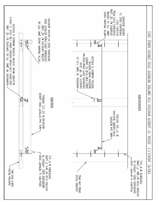
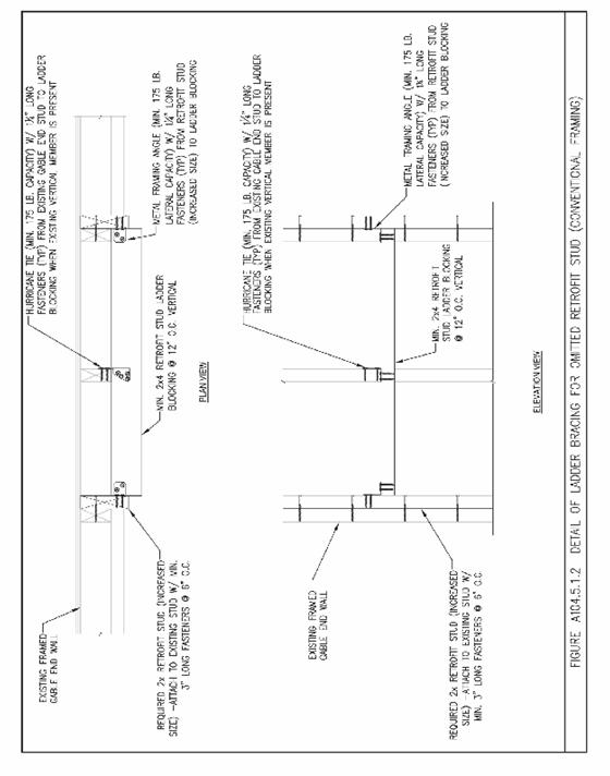
6. Ladder bracing is provided across the location of
the omitted retrofit studs as indicated in Figures A104.5.1.1 (trusses) and
A104.5.1.2 (rafters).
7. Ladder bracing shall consist of a minimum 2x4
members oriented horizontally and spaced at 12-inches on center
vertically. Ladder bracing shall be
attached to each adjacent retrofit stud with a metal framing angle with a
minimum lateral capacity of 175 lbs.
Ladder bracing shall be attached to the existing stud at the location of
the omitted retrofit stud with a metal hurricane tie with a minimum capacity of
175 lbs.
8. Where ladder bracing spans across a gable end
vent, no attachment to the gable end vent framing shall be required.
9. Notching of the ladder bracing shall not be
permitted.
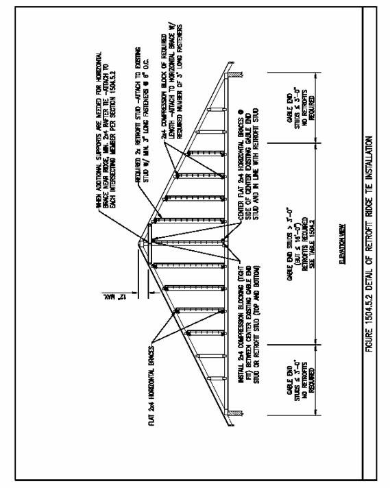
A104.5.2 Retrofit
ridge ties. When obstructions along the ridge
of the roof obstruct the installation of a horizontal brace for one or more
studs near the middle of the gable wall, retrofit ridge ties may be used to
provide support for the required horizontal brace. Retrofit
ridge tie members shall be installed a maximum of 12 inches below the existing
ridge line. The retrofit ridge tie
members shall be installed across a minimum of three bays to permit fastening
of the horizontal brace. A minimum of a
2x4 member shall be used for each ridge tie and fastening shall consist of two
3-inch long wood screws, four 3-inch long 10d nails or two 3-1/2 inch long 16d
nails driven through and clinched at each top chord or web member intersected
by the ridge tie as illustrated in Figure A104.5.2.
A104.5.3
Notching of retrofit studs. Retrofit studs may be notched in one location
along the height of the stud member provided that all of the following
conditions are met.
1. The retrofit stud to be notched shall be
sized such that the remaining depth of the member at the location of the notch
(including cut lines) shall not be less than that required by Table A104.2.
2. The notched retrofit stud shall not be
spliced within 12 inches of the location of the notch. The splicing member shall not be notched and
shall be installed as indicated in Figure A104.3.
3. The length of the flat metal straps
indicated in Table A104.2 shall be increased by the increased depth of the
notched retrofit stud member to be installed.
4. The height of the notch shall not exceed
12 inches vertically as measured at the depth of the notch.
5. The notched retrofit stud member shall be
fastened to the side of the existing gable end wall studs in accordance with
Section A104.3.1. Two additional 3-inch
fasteners (#8 wood screws or 10d nails) shall be installed on each side of the
notch in addition to those required by Section A104.3.1.
A104.6 Connection
of gable end wall to wall below. The bottom chords or bottom members of wood
framed gable end walls shall be attached to the wall below using one of the
methods prescribed in Sections A104.6.1 or A104.6.2. The particular method chosen shall correspond
to the framing system and type of wall construction encountered. Due to access considerations, this retrofit
needs to be carried out before any of the other gable end retrofit activities
referenced in Sections A104.2, A104.3, A104.4 or A104.5.
A104.6.1 Truss
gable end wall. The bottom chords of the gable
end wall shall be attached to the wall below using right angle gusset brackets
consisting of 14 gage or thicker material with a minimum load capacity of 350
lbs perpendicular to the plane of either face of the connector. The right angle gusset brackets shall be
installed throughout the portion of the gable end where the gable end wall
height is greater than 3 feet at the spacing specified in Table A104.6. A minimum of two of the fasteners specified
by the manufacturer shall engage the body of the bottom chord. Connection to the wall below shall be by one
of the methods listed below:
1. For a wood frame wall below, the two
fasteners into the top of the wall below that are closest to the face of the
gable end bottom chord shall be 4-1/2 inches long and of the same diameter and
style specified by the bracket manufacturer.
Other fasteners shall be consistent with the bracket manufacturer’s
specifications for size, style and length.
2. For a concrete or masonry wall below
without a sill plate, the fasteners into the wall shall be consistent with the
bracket manufacturer’s specifications for fasteners installed in concrete or
masonry.
3. For a concrete or masonry wall below with
a 2x sill plate, the fasteners into the wall below shall be of the diameter and
style specified by the bracket manufacturer for concrete or masonry
connections; but, long enough to pass through the wood sill plate and provide
the required embedment into the concrete or masonry below. Alternatively, the bracket can be anchored to
the sill plate using fasteners consistent with the bracket manufacturer’s
specifications for wood connections provided, the sill plate is anchored to the
wall on each side of the bracket by a 1/4-inch diameter masonry screw with a
2-1/2 inch embedment into the concrete or masonry wall. ¼-inch washers shall be placed under the
heads of the masonry screws.
A104.6.2
Conventionally framed gable end wall. Each stud in a conventionally framed gable
end wall, throughout the length of the gable end wall where the wall height is
greater than 3-feet, shall be attached to the bottom or sill plate using a stud
to plate connector. The bottom or sill
plate shall then be connected to the wall below using one of the methods listed
below:
1. For a wood frame wall below, the sill or bottom plate shall be
connected to the top plates below using ¼-inch diameter screws 4-1/2 inches
long. The fasteners shall be installed
at the spacing indicated in Table A104.6.
2. For a concrete or masonry wall below, the sill or bottom plate shall
be connected to the concrete or masonry wall below using ¼-inch diameter
concrete or masonry screws of sufficient length to provide a 2-1/2 inch
embedment into the top of the concrete or masonry wall. The fasteners shall be installed at the
spacing indicated in Table A104.6.